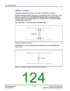
GR 1089–Core
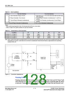
Table 4.1 Test Conditions
Test
Two-wire Interface
Four-wire Interface
A
1. Tip to Generator, Ring to Ground
2. Ring to Generator, Tip to Ground
3. Tip and Ring to Generator simultaneously
1. Each lead (T, R, T1, R1) to the Generator with the other three
leads grounded
2. Tip and Ring to Generator, simultaneously; T1 and R1 to
Ground
3. T1 and R1 to Generator, simultaneously; Tip and Ring to
Ground
B
Tip and Ring to Generator simultaneously
T, R, T1, R1 to Generator simultaneously
Notes:
•
•
When performing longitudinal tests, the test generator will have a dual output.
Refer to Table 4.2 for switch positions for each test condition.
Table 4.2 Connections to Test Generator
Condition
Condition A-1 of Table 4.1
Condition A-2 of Table 4.1
Condition A-3 of Table 4.1
S1
Closed
Open
S2
S3
Open
Closed
Closed
S4
Open
Closed
Open
Closed
Open
Open
Closed
Note: Other outside plant leads associated with the unit should be grounded during the test and the test repeated with these leads
terminated as in service. Leads that do not connect to outside plant should be terminated as appropriate for the operating
mode(s) of the unit.
S1
S3
T
Tip
E
R
M
Limiting
Resistance
(If Specified)
S2
S4
Switch Unit
Under Test
Ring
T
E
R
M
Voltage
Source
Associated
Outside
Plant
Leads
Test Generator
Figure 4.1 Connection Appearances
Passing Criteria
Passing criteria for the First Level Lightning Surge Test and the First Level AC Power Fault
Test is that the EUT will not be damaged and that it will operate as intended after the stress
is removed. Passing criteria for the Second Level Lightning Surge Test and Second Level
http://www.teccor.com
+1 972-580-7777
4 - 4
© 2002 Teccor Electronics
SIDACtor Data Book and Design Guide
®

 TECCOR [ TECCOR ELECTRONICS ]