ICM-20690
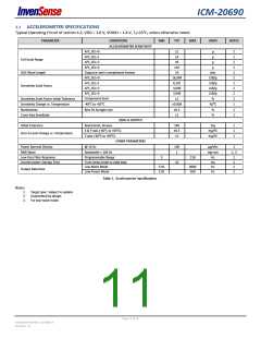
3.2 ACCELEROMETER SPECIFICATIONS
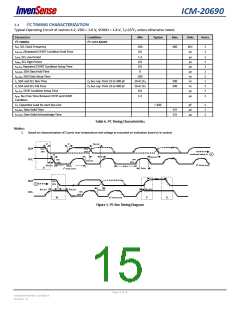
Typical Operating Circuit of section 4.2, VDD = 1.8 V, VDDIO = 1.8 V, TA=25°C, unless otherwise noted.
PARAMETER
CONDITIONS
MIN
TYP
MAX
UNITS
NOTES
ACCELEROMETER SENSITIVITY
AFS_SEL=0
AFS_SEL=1
AFS_SEL=2
AFS_SEL=3
±2
±4
g
g
2
2
2
2
2
2
2
2
2
1
1
1
1
Full-Scale Range
±8
g
±16
g
ADC Word Length
Output in two’s complement format
AFS_SEL=0
16
bits
LSB/g
LSB/g
LSB/g
LSB/g
%
16,384
8,192
4,096
2,048
±1
AFS_SEL=1
Sensitivity Scale Factor
AFS_SEL=2
AFS_SEL=3
Component-level
Sensitivity Scale Factor Initial Tolerance
Sensitivity Change vs. Temperature
Nonlinearity
-40°C to +85°C
±0.008
±0.3
±1
%/ºC
%
Best Fit Straight Line
Cross-Axis Sensitivity
%
ZERO-G OUTPUT
Initial Tolerance
Board-level, all axes
±40
±0.5
±1
mg
1
1
1
X & Y-axis (-40°C to +85°C)
Z-axis (-40°C to +85°C)
mg/ºC
mg/ºC
Zero-G Level Change vs. Temperature
OTHER PARAMETERS
Power Spectral Density
RMS Noise
@ 10 Hz
100
1
µg/√Hz
1
Bandwidth = 100 Hz
mg-rms
1, 3
Low-Pass Filter Response
Accelerometer Startup Time
Programmable Range
From sleep mode to valid data
Low-Noise Mode
5
218
Hz
ms
Hz
Hz
2
2
2
2
10
3.91
3.91
4000
500
Output Data Rate
Low-Power Mode
Table 2. Accelerometer Specifications
Notes:
1. Target spec. Subject to update.
2. Guaranteed by design.
3. For low-noise mode.
Page 11 of 76
Document Number: DS-000178
Revision: 1.0

 TDK [ TDK ELECTRONICS ]