General
Specifications
C Series – General Application
No.
7
Item
Performance
Test or Inspection Method
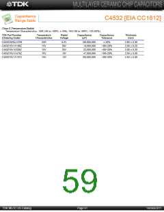
Temperature
Characteristics
Temperature coefficient shall be calculated based on
values at 25ºC and 85ºC temperature.
T.C. Temperature Coefficient
C0G 0 ± 30 (ppm/ºC)
Capacitance drift
of Capacitance
(Class 1)
Measuring temperature below 20ºC shall be -10ºC and
-25ºC.
Within ± 0.2% or ±0.05pF, whichever
larger.
8
Temperature
Characteristics
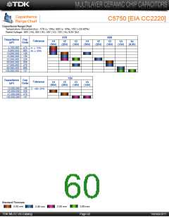
Capacitance Change (%)
Capacitance shall be measured by the steps shown in
the following table after thermal equilibrium is obtained
for each step.
No Voltage Applied
of Capacitance
(Class 2)
X5R: ± 15%
X7R: ± 15%
X6S: ± 22%
X7S: ± 22%
X7T: +22/-33%
Y5V: + 22/-82%
∆C be calculated ref. STEP 3 reading
Step
Temperature (ºC)
1
2
3
4
Reference temp. ± 2
Min. operating temp. ± 2
Reference temp. ± 2
Max. operating temp. ± 2
Measuring voltage: 0.1, 0.2, 0.5, 1.0Vrms
.
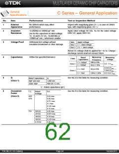
9
Robustness of
Terminations
No sign of termination coming off,
breakage of ceramic, or other abnormal
signs.
Reflow solder the capacitor on P.C. board (shown in
Appendix 1a or Appendix 1b) and apply a pushing
force of 2N (C0603, C1005) or 5N (C1608, C2012,
C3216, C3225, C4532, C5750) for 10±1s.
Pushing force
P.C. board
Capacitor
10
Bending
No mechanical damage.
Reflow solder the capacitor on P.C. board (shown in
Appendix 2a or Appendix 2b) and bend it for 1mm.
20
50
F
R230
1
45
45
Unit: mm
TDK MLCC US Catalog
Page 65
Version B11

 TDK [ TDK ELECTRONICS ]