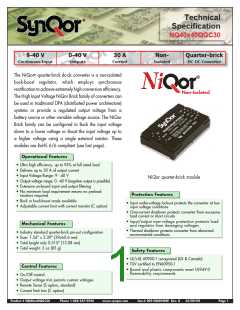
9 - 40 V
0 - 40 V
30 A
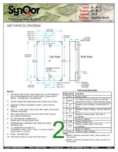
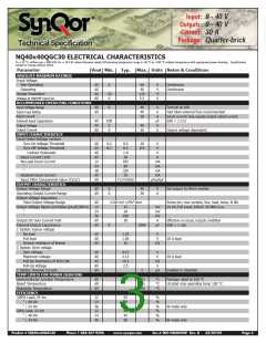
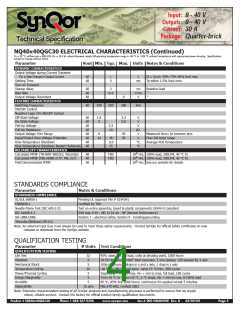
Input:
Outputs:
Current:
Package:
Quarter-brick
Technical Specification
APPLICATION CONSIDERATIONS
Vin-/
Vout+
Vin+
Cin1
Cin2
Limited output voltage resolution: The internal voltage
control feedback loop has limited resolution. Therefore, the
output voltage will exhibit discrete steps as the loop responds
to changes in line, load, trim, or remote sense. For instance,
on close examination, the startup ramp has a “stair-step”
shape. Likewise, a load transient response will be composed
of multiple discrete steps.
1
2
8
Vout+
SENSE+
TRIM
SENSE-
Vout-
Vin+
7
6
5
Cout1
Vout-
ENABLE
Dc/dc
converter
Rtrim-up
3
4
Vin-
Input filtering: These modules should be connected to a
low-impedance source. A highly inductive source can affect the
stability of the module. An input capacitance must be placed
directly adjacent to the input pin of the module, to minimize
input ripple voltage and ensure module stability.
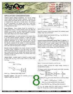
Figure B: Negative output setup
Using this negative output setup impacts the available output
voltage range and current limit.
The output voltage range becomes 0 to Vmax - Vin, and the cur-
Output capacitance: For stable operation of the module, there
is no extra external capacitor required. To reduce the output
ripple and improve dynamic response to a step load change,
additional capacitance at the output can be used. Low ESR
polymer and ceramic capacitors are recommended to improve
the dynamic response of the module. In many applications,
however, additional external output capacitance is a requirement
which will cause the startup time to change.
rent limit is scaled by:
Vin
(Vin + Vout)
Current monitor/trimmable current limit (C option): In
addition to voltage trim, the C option offers an adjustable current
limit input and a current monitor output. The C option also
includes an ideal diode circuit in series with the Vout+ pin that
prevents reverse current flow. This enables applications such as
battery charging, current sharing, and current read back.
Remote sense (S option): Vout remote sensing is provided
to achieve proper regulation at the load points and reduce
effects of distribution losses on output line. In the event of an
open remote sense line, the module shall maintain local sense
regulation through an internal resistor. The module shall correct
for a total of 10% Vout.
Dc/dc
converter
Vout+
Vin+
Cin
1
2
8
7
6
5
Vout+
Vin+
IMON
VTRIM
IMON
Cout
ENABLE
Current limit: Available power is limited by output current
in buck mode (Vin>Vout), but by input current in boost mode
(Vin<Vout).
ITRIM
3
4
Vin-
Vout-
RadjIlim Rtrim-up
Vout-
Vin-
for Vin >Vout,
Figure C: Current monitor/trimmable current limit setup
Ilimit = 1.2 x Imax
The Rtrim-up resistor increases the output voltage, identical in
function to the S option.
for Vin < Vout,
Vin
The RadjItrim resistor reduces the output current limit, according
to the following equation:
Ilimit = 1.2 x Imax
Vout
( )
0.0469 Imax + Itrim
where Imax = Maximum rated output current
RadjItrim
=
10200 - 10
(Ω)
1.153 I
+ Itrim
[(
max
) ]
Negative output: This series of converters can be set to
negative output (see Figure B).
Alternatively, the Itrim pin can be driven from an external voltage
source:
V(pin5) = 2.085(Itrim/Imax) + 0.0953
where Itrim is the desired current limit setpoint
If Ilimit is less than Itrim, then Ilimit takes precedence.
The I
pin voltage tracks the output current, as shown in
mon
figure 10. This pin has a 10kOhm output impedance.
Product # NQ40x40QGC30
Phone 1-888-567-9596
www.synqor.com
Doc.# 005-NQ4040W Rev. B
03/09/09
Page 8

 SYNQOR [ SYNQOR WORLDWIDE HEADQUARTERS ]