9 - 40 V
0 - 40 V
30 A
Input:
Outputs:
Current:
Package:
Quarter-brick
Technical Specification
100
95
90
85
80
75
70
65
60
40
35
30
25
20
15
10
5
36Vin 24Vout
24Vin 12Vout
36Vin 12Vout
24Vin 36Vout
12Vin 24Vout
12Vin 36Vout
36Vin 24Vout
24Vin 12Vout
36Vin 12Vout
24Vin 36Vout
12Vin 24Vout
12Vin 36Vout
0
0
5
10
15
20
25
30
0
5
10
15
20
25
30
Load Current (A)
Load Current (A)
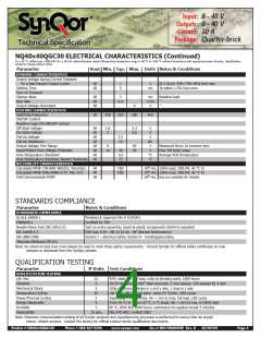
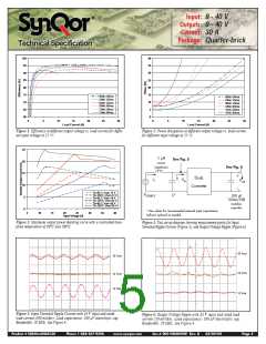
Figure 1: Efficiency at different output voltage vs. load current for differ-
Figure 2: Power dissipation at different output voltage vs. load current
for different input voltage at 25 °C
ent input voltage at 25 °C
.
.
25
20
15
10
5
1ꢀµHꢀ
See Fig. 5
sourceꢀ
impedance
See Fig. 6
iC
Dc-dc
Converter
iS
Vin
Vout
Tb=80 C; Vout=12 V
Tb=100 C; Vout=12 V
Tb=80 C; Vout=24 V
Tb=100 C; Vout=24 V
Tb=80 C; Vout=36 V
Tb=100 C; Vout=36 V
VSOURCE
C*
100ꢀµFꢀ
100mWꢀESRꢀ
tantalumꢀ
capacitor
0
*ꢀSeeꢀvaluesꢀforꢀrecommendedꢀexternalꢀinputꢀcapacitance.ꢀ
Inductorꢀoptionalꢀasꢀneeded.
5
10
15
20
25
30
35
40
Input Voltage (V)
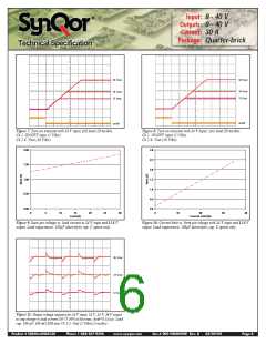
Figure 3: Maximum output power derating curve with a controlled base-
plate temperature of 80ºC and 100ºC.
Figure 4: Test set-up diagram showing measurement points for Input
Terminal Ripple Current (Figure 5), and Output Voltage Ripple (Figure 6).
36 Vout
24 Vout
36 Vout
24 Vout
12 Vout
12 Vout
Figure 5: Input Terminal Ripple Current with 24 V input and rated
Figure 6: Output Voltage Ripple with 24 V input and rated load
load current (500 mA/div). Load capacitance: 100
Bandwidth: 20 MHz. See Figure 4.
µF electrolytic cap.
current (50 mV/div). Load capacitance: 100
Bandwidth: 20 MHz. See Figure 4.
µF electrolytic cap.
Product # NQ40x40QGC30
Phone 1-888-567-9596
www.synqor.com
Doc.# 005-NQ4040W Rev. B
03/09/09
Page 5

 SYNQOR [ SYNQOR WORLDWIDE HEADQUARTERS ]