9 - 40 V
0 - 40 V
30 A
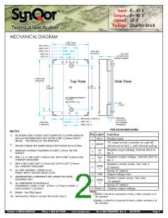
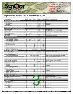
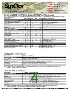
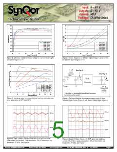
Input:
Outputs:
Current:
Package:
Quarter-brick
Technical Specification
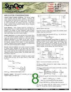
Alternatively, the TRIM pin can be driven from an external
voltage source:
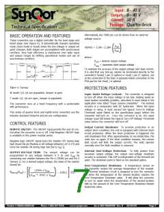
BASIC OPERATION AND FEATURES
These converters use a digital controller for the buck stage and
boost stage (see Figure A). It automatically changes operating
mode (buck mode or boost) when the line voltage or output set
point changes. Both stages are accomplished with synchronous
rectifiers. Very high efficiency is maintained over wide input
and output ranges by shifting operational modes and use of
synchronous rectifiers.
Vout
V(pin6) = 2.366 – 2.314
2.284
Vmax
( )
where:
V
out = desired output voltage
Vin+
Vout+
Vmax = maximum rated output voltage
Loutput
Cout1
GATE_Q3
L
Linput
GATE_Q1
JUMPER
Q3
Q4
Q1
Q2
To maintain the accuracy of the output voltage over load current,
it is vital that any trim-up resistor be terminated directly to the
converter’s Sense(-) pin (S option) or Vout(-) pin (C option), not
at the connection to the load. A separate Kelvin connection to the
PCB pad for the Vout(-) is optimal.
Cout2
Cin1
Cin2
GATE_Q4
GATE_Q2
Vin-
Vout-
Figure A: Topology
PROTECTION FEATURES
W mode: Q3, Q4 are populated, Jumper is open.
T mode: Q3, Q4 are open, Jumper is populated.
Input Under-Voltage Lockout: The converter is designed
to turn off when the input voltage is too low, helping avoid an
input system instability problem, described in more detail in the
application note titled “Input System Instability”. The lockout
circuitry is a comparator with DC hysteresis. When the input
voltage is rising, it must exceed the typical Turn-On Voltage
Threshold value (listed on the specification page) before the
converter will turn on. Once the converter is on, the input
voltage must fall below the typical Turn-Off Voltage Threshold
value before the converter will turn off.
The converter runs at a fixed frequency with a predictable
EMI performance.
This series of quarter-brick and eighth-brick converters use the
industry standard footprint and pin-out configuration.
CONTROL FEATURES
REMOTE ON/OFF: The ON/OFF input permits the user to con-
trol when the converter is on or off. Only Negative ON/OFF logic
is available in this power module series.
Output Current Shutdown: To provide protection in an
output short condition, the unit is equipped with internal short
circuit protection. When the short protection is triggered, the
unit shutdowns first. After approximately 16 ms inhibit time, the
units turn on again. If the short condition remains, the current
limit circuit will limit the output current. The units operate
normally once the fault condition is removed.
Negative logic ON/OFF signal turns the module OFF during logic
high (leave the pin floating or set voltage between 1.8~3.3 V) and
turns the module ON during logic low [tie to Vin(-)].
Internal Over-Voltage Protection: To fully protect from
excessive output voltage, the output over-voltage shutdown
circuitry is contained. This OVP is independent of the trimmed set
point. The shutdown point is fixed on the standard option.
OUTPUT VOLTAGE TRIM: The output voltage can be
programmed to any voltage between 0 V dc and Vmax by
connecting one resistor between the Pin 6 (TRIM) pin and Pin 5
[Sense(-)]. For a desired output voltage, the value of the resistor
should be:
Over-Temperature Shutdown: A temperature sensor on
the converter senses the average temperature of the module.
The thermal shutdown circuit is designed to turn the converter
off when the temperature at the sensed location reaches the
Over-Temperature Shutdown value. It will allow the converter
to turn on again when the temperature of the sensed location
falls by the amount of the Over-Temperature Shutdown Restart
Hysteresis value.
111198030 x Vmax
_
R
trim-up(Vout) =
(Ω)
10912
+
V
.00.504538 x V
max
[( ) ]
out
Product # NQ40x40QGC30
Phone 1-888-567-9596
www.synqor.com
Doc.# 005-NQ4040W Rev. B
03/09/09
Page 7

 SYNQOR [ SYNQOR WORLDWIDE HEADQUARTERS ]