MQFL-28-05S
Output:
Current:
5.0 V
24 A
Technical Specification
CURRENT SHARE: When several MQFL converters are placed
in parallel to achieve either a higher total load power or N+1
redundancy, their SHARE pins (pin 11) should be connected
together. The voltage on this common SHARE node represents
the average current delivered by all of the paralleled converters.
Each converter monitors this average value and adjusts itself so
that its output current closely matches that of the average.
100,000
10,000
1,000
100
Since the SHARE pin is monitored with respect to the OUTPUT
RETURN (pin 8) by each converter, it is important to connect all
of the converters’ OUTPUT RETURN pins together through a low
DC and AC impedance. When this is done correctly, the con-
verters will deliver their appropriate fraction of the total load cur-
rent to within +/- 10% at full rated load.
0
0.1
0.2
0.3
0.4
0.5
0.6
Increase in Vout (V)
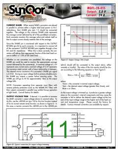
Whether or not converters are paralleled, the voltage at the
SHARE pin could be used to monitor the approximate average
current delivered by the converter(s). A nominal voltage of 1.0V
represents zero current and a nominal voltage of 2.2V represents
the maximum rated current, with a linear relationship in between.
The internal source resistance of a converter’s SHARE pin signal
is 2.5 kΩ. During an input voltage fault or primary disable event,
the SHARE pin outputs a power failure warning pulse. The
SHARE pin will go to 3V for approximately 14ms as the output
voltage falls.
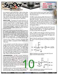
Figure E: Output Voltage Trim Graph
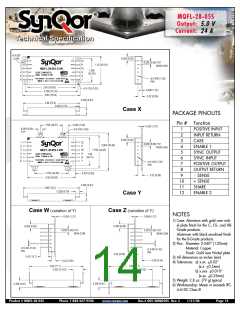
(which should still be connected to the output return, either
remotely or locally). The value of the trim resistor should be cho-
sen according to the following equation or from Figure E:
Vnom
Rtrim = 100 x
[
Vout – Vnom – 0.025
]
where:
Vnom = the converter’s nominal output voltage,
Vout = the desired output voltage (greater than Vnom), and
Rtrim is in Ohms.
NOTE: Converters operating from separate input filters with
reverse polarity protection (such as the MQME-28-T filter) with
their outputs connected in parallel may exhibit hiccup operation
at light loads. Consult factory for details.
As the output voltage is trimmed up, it produces a greater voltage
stress on the converter’s internal components and may cause the
converter to fail to deliver the desired output voltage at the low
end of the input voltage range at the higher end of the load cur-
rent and temperature range. Please consult the factory for
details. Factory trimmed converters are available by request.
OUTPUT VOLTAGE TRIM: If desired, it is possible to increase
the MQFL converter’s output voltage above its nominal value. To
do this, use the +SENSE pin (pin 10) for this trim function instead
of for its normal remote sense function, as shown in Figure D. In
this case, a resistor connects the +SENSE pin to the –SENSE pin
1
12
+VIN
ENA 2
2
11
IN RTN
SHARE
3
10
CASE
+ SNS
Rtrim
4
5
6
9
+
–
28Vdc
ENA 1
– SNS
–
8
7
SYNC OUT
SYNC IN
OUT RTN
+VOUT
open
means
on
Load
+
Figure D: Typical connection for output voltage trimming.
Product # MQFL-28-05S
Phone 1-888-567-9596
www.synqor.com
Doc.# 005-2MQ050S Rev. C
1/21/08
Page 11

 SYNQOR [ SYNQOR WORLDWIDE HEADQUARTERS ]