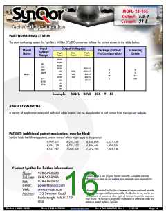
MQFL-28-05S
Output:
Current:
5.0 V
24 A
Technical Specification
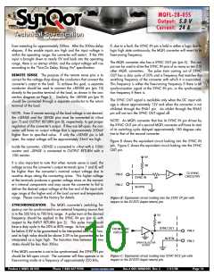
INPUT UNDER-VOLTAGE LOCKOUT: The MQFL converter
has an under-voltage lockout feature that ensures the converter
will be off if the input voltage is too low. The threshold of input
voltage at which the converter will turn on is higher that the
threshold at which it will turn off. In addition, the MQFL converter
will not respond to a state of the input voltage unless it has
remained in that state for more than about 200µs. This hysteresis
and the delay ensure proper operation when the source imped-
ance is high or in a noisy environment.
The Mil-HDBK-1547A component derating guideline calls for a
maximum component temperature of 105ºC. Figure 5 therefore
has one power derating curve that ensures this limit is main-
tained. It has been SynQor’s extensive experience that reliable
long-term converter operation can be achieved with a maximum
component temperature of 125ºC. In extreme cases, a maximum
temperature of 145ºC is permissible, but not recommended for
long-term operation where high reliability is required. Derating
curves for these higher temperature limits are also included in
Figure 5. The maximum case temperature at which the convert-
er should be operated is 135ºC.
INPUT OVER-VOLTAGE SHUTDOWN: The MQFL converter
also has an over-voltage feature that ensures the converter will be
off if the input voltage is too high. It also has a hysteresis and
time delay to ensure proper operation.
When the converter is mounted on a metal plate, the plate will
help to make the converter’s case bottom a uniform temperature.
How well it does so depends on the thickness of the plate and on
the thermal conductance of the interface layer (e.g. thermal
grease, thermal pad, etc.) between the case and the plate.
Unless this is done very well, it is important not to mistake the
plate’s temperature for the maximum case temperature. It is easy
for them to be as much as 5-10ºC different at full power and at
high temperatures. It is suggested that a thermocouple be
attached directly to the converter’s case through a small hole in
the plate when investigating how hot the converter is getting.
Care must also be made to ensure that there is not a large ther-
mal resistance between the thermocouple and the case due to
whatever adhesive might be used to hold the thermocouple in
place.
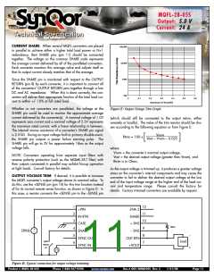
BACK-DRIVE CURRENT LIMIT: Converters that use MOSFETs
as synchronous rectifiers are capable of drawing a negative cur-
rent from the load if the load is a source of short- or long-term
energy. This negative current is referred to as a “back-drive cur-
rent”.
Conditions where back-drive current might occur include paral-
leled converters that do not employ current sharing, or where the
current share feature does not adequately ensure sharing during
the startup or shutdown transitions. It can also occur when con-
verters having different output voltages are connected together
through either explicit or parasitic diodes that, while normally off,
become conductive during startup or shutdown. Finally, some
loads, such as motors, can return energy to their power rail.
Even a load capacitor is a source of back-drive energy for some
period of time during a shutdown transient.
INPUT SYSTEM INSTABILITY: This condition can occur
because any DC/DC converter appears incrementally as a
negative resistance load. A detailed application note titled
“Input System Instability” is available on the SynQor website
which provides an understanding of why this instability arises,
and shows the preferred solution for correcting it.
To avoid any problems that might arise due to back-drive current,
the MQFL converters limit the negative current that the converter
can draw from its output terminals. The threshold for this back-
drive current limit is placed sufficiently below zero so that the
converter may operate properly down to zero load, but its
absolute value (see the Electrical Characteristics page) is small
compared to the converter’s rated output current.
THERMAL CONSIDERATIONS: Figure 5 shows the suggested
Power Derating Curves for this converter as a function of the case
temperature and the maximum desired power MOSFET junction
temperature. All other components within the converter are cool-
er than its hottest MOSFET, which at full power is no more than
20ºC higher than the case temperature directly below this MOS-
FET.
Product # MQFL-28-05S
Phone 1-888-567-9596
www.synqor.com
Doc.# 005-2MQ050S Rev. C
1/21/08
Page 12

 SYNQOR [ SYNQOR WORLDWIDE HEADQUARTERS ]