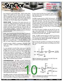
MQFL-28-05S
Output:
Current:
5.0 V
24 A
Technical Specification
from restarting for approximately 300ms. After the 300ms delay
elapses, if the enable inputs are high and the input voltage is
within the operating range, the converter will restart. If the VIN
input is brought down to nearly 0V and back into the operating
range, there is no startup inhibit, and the output voltage will rise
according to the "Turn-On Delay, Rising Vin" specification.
If, due to a fault, the SYNC IN pin is held in either a logic low or
logic high state continuously, the MQFL converter will revert to its
free-running frequency.
The MQFL converter also has a SYNC OUT pin (pin 5). This out-
put can be used to drive the SYNC IN pins of as many as ten (10)
other MQFL converters. The pulse train coming out of SYNC
OUT has a duty cycle of 50% and a frequency that matches the
switching frequency of the converter with which it is associated.
This frequency is either the free-running frequency if there is no
synchronization signal at the SYNC IN pin, or the synchroniza-
tion frequency if there is.
REMOTE SENSE: The purpose of the remote sense pins is to
correct for the voltage drop along the conductors that connect the
converter’s output to the load. To achieve this goal, a separate
conductor should be used to connect the +SENSE pin (pin 10)
directly to the positive terminal of the load, as shown in the con-
nection diagram on Page 2. Similarly, the –SENSE pin (pin 9)
should be connected through a separate conductor to the return
terminal of the load.
The SYNC OUT signal is available only when the DC input volt-
age is above approximately 12V and when the converter is not
inhibited through the ENA1 pin. An inhibit through the ENA2
pin will not turn the SYNC OUT signal off.
NOTE: Even if remote sensing of the load voltage is not desired,
the +SENSE and the -SENSE pins must be connected to +Vout
(pin 7) and OUTPUT RETURN (pin 8), respectively, to get proper
regulation of the converter’s output. If they are left open, the con-
verter will have an output voltage that is approximately 200mV
higher than its specified value. If only the +SENSE pin is left
open, the output voltage will be approximately 25mV too high.
NOTE: An MQFL converter that has its SYNC IN pin driven by
the SYNC OUT pin of a second MQFL converter will have its start
of its switching cycle delayed approximately 180 degrees rela-
tive to that of the second converter.
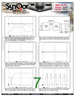
Figure B shows the equivalent circuit looking into the SYNC IN
pin. Figure C shows the equivalent circuit looking into the SYNC
OUT pin.
Inside the converter, +SENSE is connected to +Vout with a 100Ω
resistor and –SENSE is connected to OUTPUT RETURN with a
10Ω resistor.
5V
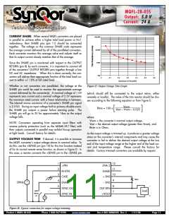
It is also important to note that when remote sense is used, the
voltage across the converter’s output terminals (pins 7 and 8) will
be higher than the converter’s nominal output voltage due to
resistive drops along the connecting wires. This higher voltage
at the terminals produces a greater voltage stress on the convert-
er’s internal components and may cause the converter to fail to
deliver the desired output voltage at the low end of the input volt-
age range at the higher end of the load current and temperature
range. Please consult the factory for details.
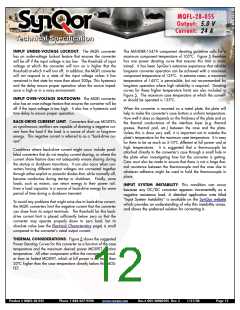
5K
TO SYNC
CIRCUITRY
PIN 6
SYNC IN
IN RTN
5K
PIN 2
Figure B: Equivalent circuit looking into the SYNC IN pin with
respect to the IN RTN (input return) pin.
SYNCHRONIZATION: The MQFL converter’s switching fre-
quency can be synchronized to an external frequency source that
is in the 500 kHz to 700 kHz range. A pulse train at the desired
frequency should be applied to the SYNC IN pin (pin 6) with
respect to the INPUT RETURN (pin 2). This pulse train should
have a duty cycle in the 20% to 80% range. Its low value should
be below 0.8V to be guaranteed to be interpreted as a logic low,
and its high value should be above 2.0V to be guaranteed to be
interpreted as a logic high. The transition time between the two
states should be less than 300ns.
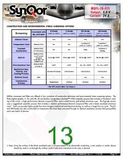
5V
5K
SYNC OUT
FROM SYNC
CIRCUITRY
PIN 5
IN RTN
PIN 2
OPEN COLLECTOR
OUTPUT
If the MQFL converter is not to be synchronized, the SYNC IN pin
should be left open circuit. The converter will then operate in its
free-running mode at a frequency of approximately 550 kHz.
Figure C: Equivalent circuit looking into SYNC OUT pin with
respect to the IN RTN (input return) pin.
Product # MQFL-28-05S
Phone 1-888-567-9596
www.synqor.com
Doc.# 005-2MQ050S Rev. C
1/21/08
Page 10

 SYNQOR [ SYNQOR WORLDWIDE HEADQUARTERS ]