SyncMOS Technologies International, Inc.
SM89T16R1
8-Bits Micro-controller
With 64KB Flash ROM & 1KB RAM & Two UART & RTC & ADC & PWM embedded
The Power Down Wake Up (PDWU) function
The device can be put into Power Down mode by writing 1 to bit PCON.1. The instruction that does this will be the
last instruction to be executed before the device goes into Power Down mode. In the Power Down mode, all the
clocks are stopped and the device comes to a halt. All activity is completely stopped and the power consumption is
reduced to the lowest possible value. In this state the ALE and PSEN pins are pulled low. The port pins output the
values held by their respective SFRs.
The SM89T16R1 will exit the Power Down mode with a reset or by a RTC (Real Time Clock) interrupt or by an
external interrupts pin enabled as level detects.
1. An external reset can be used to exit the Power Down state. The high on RST pin terminates the Power Down mode,
and restarts the clock. The program execution will restart from 0000H.
2. An external interrupt pin and RTC interrupt can be used to exit the Power Down state when the external interrupt or
RTC interrupt actives and provided the corresponding interrupt is enabled, while the global enable (EA) bit is set and
the external input has been set to a level detect mode or RTC interrupt set. If these conditions are met, then the low
level on the external pin or RTC interrupt re-starts the oscillator. Then device executes the interrupt service routine for
the corresponding external interrupt or RTC interrupt. After the interrupt service routine is completed, the program
execution returns to the instruction after the one that put the device into Power Down mode and continues from there.
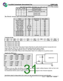
The status of external pins during Idle and Power Down:
Mode
Program
Memory
Internal
External
Internal
External
ALE
/PSEN
PORT0
PORT1
PORT2
PORT3
PORT4
Idle
Idle
Power Down
Power Down
1
1
0
0
1
1
0
0
Data
Float
Data
Float
Data
Data
Data
Data
Data
Address
Data
Data
Data
Data
Data
Data
Data
Data
Data
Data
PCON ($87H)
Bit7
Bit6
SMOD0
Bit5
Bit4
Bit3
Bit2
Bit1
PD
Bit0
IDLE
SMOD
SMOD: This bit set to ‘1’ to make the UART baud-rate double.
SMOD0: This bit define the SCON.7 and SCON1.7 use as FE (FE1) or SM0 (SM0_1)
PD: When set to ‘1’, the MCU will into Power Down mode
IDLE: When set to ‘1’, the MCU will into IDLE mode
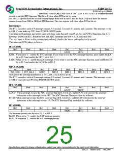
IE ($A8H)
Bit7
EA
Bit6
ES1
Bit5
ET2
Bit4
ES0
Bit3
ET1
Bit2
EX1
Bit1
ET0
Bit0
EX0
EA: When set to ‘1’, enable interrupt global.
ES1: When set to ‘1’, enable UART1 interrupt.
ET2: When set to ‘1’, enable Timer2 interrupt.
ES0: When set to ‘1’, enable UART interrupt.
ET1: When set to ‘1’, enable Timer1 interrupt.
EX1: When set to ‘1’, enable external interrupt 1.
ET0: When set to ‘1’, enable Timer0 interrupt.
EX0: When set to ‘1’, enable external interrupt 0.
IP ($B8H)
Bit7
Bit6
Bit5
PT2
Bit4
PS0
Bit3
PT1
Bit2
PX1
Bit1
PT0
Bit0
PX0
PT2: Timer2 interrupt priority.
PS0: UART interrupts priority.
Specifications subject to change without notice contact your sales representatives for the most recent information.
Ver 2.1 SM89T16R1 08/2006
27

 SYNCMOS [ SYNCMOS TECHNOLOGIES,INC ]