SyncMOS Technologies International, Inc.
SM89T16R1
8-Bits Micro-controller
With 64KB Flash ROM & 1KB RAM & Two UART & RTC & ADC & PWM embedded
U2
int 0.5sec
int 1sec
int out
4
3
5
6
D0
D1
D2
D3
D4
D5
D6
D7
Y
Y
int 0.5min
Divider 2
2
int 1min
1
Divider 16384
<Value>
Divider 2
<Value>
Divider 30
15
14
13
12
32768Hz Clock in
11
10
9
A
B
C
<Value>
<Value>
int sel0
int sel1
RTCen
7
G
74151
5 bits shif register
5 bits shif register
sec0
sec1
sec2
min0
min1
min2
second register sec3
minute register min3
sec4
sec5
min4
min5
<Value>
<Value>
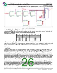
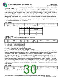
Figure 18 The RTC Block Diagram
LED Driving Capability Control
This function is set the sink current more then 10mA for each pin, 26mA for whole Port 0, 15mA for whole Port 1 or
whole Port2 or whole Port3 or whole Port4, and total 71mA for whole chip.
The SFR shown as below:
Port Name
Port0
SFR Address
$92H
Iol(max) of pre port
26 mA
Port1
$93H
15 mA
Port2
$94H
15 mA
Port3
$95H
15 mA
Port4
$96H
15 mA
Power Saving Mode
The SM89T16R1 has several features that help the user to control the power consumption of the device. The
powers saving features are basically the Power Down mode, Economy mode and the Idle mode of
operation.
Idle Mode
The user can put the device into idle mode by writing 1 to the bit PCON.0. The instruction that sets the idle bit is the
last instruction that will be executed before the device goes into Idle Mode. In the Idle Mode, the clock to the CPU is
halted, but not to the Interrupt, Timer and Serial port blocks. This forces the CPU state to be frozen; the Program
counter, the Stack Pointer, the Program Status Word, the Accumulator and the other registers hold their contents. The
ALE and PSEN pins are held high during the idle state. The port pins hold the logical states they had at the time idle
was activated. The idle mode can be terminated in two ways. Since the interrupt controller is still active, the activation
of any enabled interrupt can wake up the processor. This will automatically clear the idle bit, terminate the idle mode,
and the Interrupt Service Routine (ISR) will be executed. After the ISR, execution of the program will continue from
the instruction that put the device into idle mode.
The Idle mode can also be exited by activating the reset. The device can be put into reset either applying a high on the
external RST pin or a Power on reset condition. The external reset pin has to be held high for at least two machine
cycles to be recognized as a valid reset. In the reset condition the program counter is reset to 0000H and all the SFRs
are set to the reset condition. Since the clock is already running there is no delay and execution start immediately.
When the SM89T16R1 is exiting from an idle mode with a reset, the instruction following the one that put the device
into idle mode is not executed. So there is no danger of unexpected writes.
Specifications subject to change without notice contact your sales representatives for the most recent information.
Ver 2.1 SM89T16R1 08/2006
26

 SYNCMOS [ SYNCMOS TECHNOLOGIES,INC ]