HV9910
can be generated by a microcontroller or a pulse generator
with a duty cycle proportional to the amount of desired
light output. This signal enables and disables the converter
modulating the LED current in the PWM fashion. In this
mode, LED current can be in one of the two states: zero or
the nominal current set by the current sense resistor. It is not
possible to use this method to achieve average brightness
levels higher than the one set by the current sense threshold
level of the HV9910. By using the PWM control method of
the HV9910, the light output can be adjusted between zero
and 100%. The accuracy of the PWM dimming method is
limited only by the minimum gate pulse width, which is a
fraction of a percent of the low frequency duty cycle.
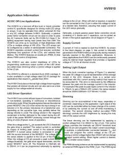
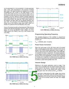
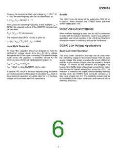
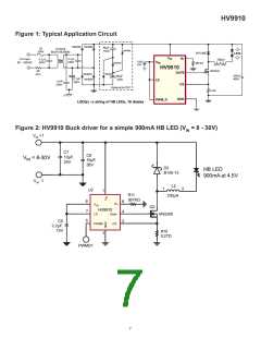
Some of the typical waveforms illustrating the PWM dimming
method used with the application circuit on page 7 are given
below. CH shows the MOSFET Drain voltage, CH2 is the
PWM sign1al to pin PWM_D and CH4 is the current in the
LED string.
0.4% PWM Ratio at 500Hz Dimming
Programming Operating Frequency
The operating frequency of the oscillator is programmed
between 25 and 300kHz using an external resistor connected
to the RT pin:
FOSC = 25000/(RT [kΩ] + 22) [kHz]
Power Factor Correction
When the input power to the LED driver does not exceed
25W, a simple passive power factor correction circuit can be
added to the HV9910 typical application circuit on page 7 in
order to pass the AC line harmonic limits of the EN61000-
3-2 standard for Class C equipment. The typical application
circuit diagram shows how this can be done without affecting
the rest of the circuit significantly. A simple circuit consisting
of 3 diodes and 2 capacitors is added across the rectified AC
line input to improve the line current harmonic distortion and
to achieve a power factor greater than 0.85.
33% PWM Ratio at 500Hz Dimming
Inductor Design
Referring to the typical application circuit on page 7 the
value can be calculated from the desired peak-to-peak LED
ripple current in the inductor. Typically, such ripple current
is selected to be 30% of the nominal LED current. In the
example given here, the nominal current ILED is 350mA.
The next step is determining the total voltage drop across
the LED string. For example, when the string consists of 10
High-Brightness LEDs and each diode has a forward voltage
drop of 3.0V at its nominal current; the total LED voltage
VLEDS is 30V.
95% PWM Ratio at 500Hz Dimming
5

 SUPERTEX [ Supertex, Inc ]