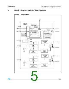
Block diagram and pin descriptions
VN5770AK-E
Table 2.
No
Pin descriptions
NAME
FUNCTION
Drain of Switch 3 (low-side switch)
1, 3, 25, 28 DRAIN 3
2
INPUT 3
N.C.
Input of Switch 3 (low-side switch)
Not Connected
4, 11
Drain of Switches 1 and 2 (high-side switches) and Power Supply
Voltage
5, 10, 19, 24 VCC
6
7
8
GND
Ground of Switches 1 and 2 (high-side switches)
Input of Switch 1 (high-side switches)
Input of Switch 2 (high-side switch)
INPUT 1
INPUT 2
CURRENT
SENSE
Analog current sense pin, delivers a current proportional to the
load current
9
12, 14, 15, 18 DRAIN 4
Drain of switch 4 (low-side switch)
Input of Switch 4 (low-side switch)
Source of Switch 4 (low-side switch)
Source of Switch 2 (high-side switch)
Source of Switch 1 (high-side switch)
Source of Switch 3 (low-side switch)
13
INPUT 4
16, 17
20, 21
22, 23
26, 27
SOURCE 4
SOURCE 2
SOURCE 1
SOURCE 3
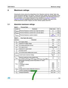
Figure 2.
Configuration diagram (Top view)
6/31

 STMICROELECTRONICS [ ST ]