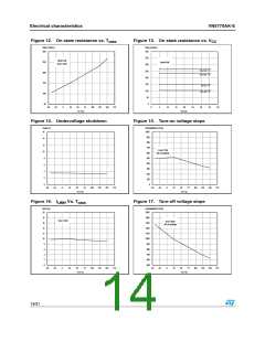
Electrical characteristics
VN5770AK-E
Table 8.
Symbol
Logic input
Parameter
Test Conditions
Min. Typ. Max. Unit
VIL
IIL
Input low level voltage
0.9
V
Low level input current VIN=0.9V
Input high level voltage
1
µA
V
VIH
IIH
2.1
High level input current VIN=2.1V
10
7
µA
Input hysteresis
voltage
VI(hyst)
0.25
5.5
V
IIN=1mA
Input clamp voltage
IIN=-1mA
V
V
VICL
-0.7
(1)
Table 9.
Symbol
Protection and diagnostics
Parameter
Test Conditions
VCC=13V
5V<VCC<36V
Min.
Typ.
Max. Unit
6
8.5
12
12
A
A
DC Short circuit
current
IlimH
Short circuit current
during thermal cycling
IlimL
VCC=13V; TR<Tj<TTSD
3.5
A
TTSD
TR
Shutdown temperature
Reset temperature
150
175
200
°C
°C
TRS + 1 TRS + 5
135
Thermal reset of
STATUS
TRS
°C
°C
V
Thermal hysteresis
(TTSD-TR)
THYST
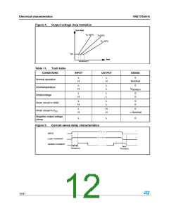
VDEMAG
7
Turn-off output voltage
clamp
IOUT=1A; VIN=0; L=20mH
VCC-41 VCC-46 VCC-52
IOUT=0.03A; Tj=-40°C to
150°C
Output voltage drop
limitation
VON
25
mV
(see Figure 4.)
1. To ensure long term reliability under heavy overload or short circuit conditions, protection and related
diagnostic signals must be used together with a proper software strategy. If the device is subjected to
abnormal conditions, this software must limit the duration and number of activation cycles
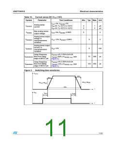
Table 10. Current sense (8V<V <16V)
CC
Symbol
Parameter
Test Conditions
Min. Typ. Max. Unit
IOUT=0.080A; VSENSE=0.5V;
Tj=-40°C to 50°C
K0
IOUT/ISENSE
850 1450 2020
IOUT=0.35A; VSENSE=0.5V;
Tj=-40°C to 150°C
K1
IOUT SENSE
/I
940 1360 1900
1040 1360 1680
Tj=25°C to 150°C
IOUT=3A; VSENSE=4V;
Tj=-40°C to 150°C
K2
K3
IOUT/ISENSE
1200 1270 1350
1180 1260 1330
IOUT=5A; VSENSE=4V;
Tj=-40°C to 150°C
IOUT SENSE
/I
10/31

 STMICROELECTRONICS [ ST ]