Application information
VN5770AK-E
4
Application information
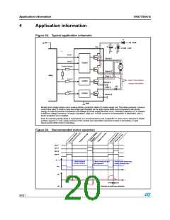
Figure 33. Typical application schematic
D
Vbatt
5V
Vcc
C
Z
Vz 32V > 40V
Input 1
Source 1
Input 2
Control
Current Sense
M
Source 2
Drain 3
Micro
Input 3
Control
Motor inducuctance
energy recirculation
Source 3
Drain 4
I M
Input 4
Control
Source 4
GND
Mostly motor bridge drivers use a reverse battery protection diode (D) inside supply rail. This diode prevents a reverse
current flow back to Vbatt in case the bridge gets disabled via the logic inputs while motor inductance still carries
energy. In order to prevent a hazardous overvoltage at circuit supply terminal (Vcc), a blocking capacitor (C) is needed
to limit the voltage overshoot. As basic orientation, 50µF per 1A load current in recommended. In alternative, also a
Zener protection (Z) is suitable.
Even if a reverse polarity diode is not present, it is recommended to use a capacitor or zener at Vcc because a similar
problem appears in case supply terminal of the module has intermittent electrical contact to the battery or gets
disconnected while motor is operating.
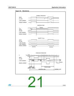
Figure 34. Recommended motor operation
Input
Input
Input
Input
1
2
3
4
V z
F lyback clam ped
by Zener diode
F lyback energy charged
into capacitor
F lyback spike during cross
current protection tim e
Z
C
V cc
t
+I
M
M
t
-
I
D ead tim e to avoid cross conduction
20/31

 STMICROELECTRONICS [ ST ]