VN5770AK-E
Package and thermal data
5
Package and thermal data
5.1
SO-28 thermal data
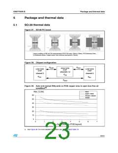
Figure 37. SO-28 PC board
Layout condition of Rth and Zth measurements (PCB FR4 area= 58mm x 58mm, PCB thickness=2mm,
Cu thickness=35mm, Copper areas: from minimum pad layout to 16cm2).
Figure 38. Chipset configuration
RthAB
RthAC
HIGH SIDE
CHIP
channels 1,2
LOW SIDE
CHIP
LOW SIDE
CHIP
channel 3
channel 4
RthA
RthB
RthC
RthBC
Figure 39. Auto and mutual Rthj-amb vs PCB copper area in open box free air
(a)
condition
RthA
Rth (˚C/W)
RthB = RthC
60
RthAB = RthAC
RthBC
50
40
30
20
10
0
0
1
2
3
4
5
6
7
Cu Area (refer to PCB layout)
a. See Figure 38. For more detailed information see Table 18 and Table 19.
23/31

 STMICROELECTRONICS [ ST ]