Package and thermal data
VN5770AK-E
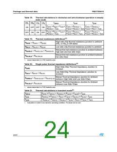
Table 18. Thermal calculations in clockwise and anti-clockwise operation in steady-
state mode
HS1 HS2 LS3 LS4
TjHS12
TjLS3
TjLS4
PdHS1 x RthHS + PdLS4
RthHSLS + Tamb
x
x
PdHS1 x RthHSLS
PdLS4 x RthLSLS + Tamb PdLS4 x RthLS + Tamb
+
PdHS1 x RthHSLS +
ON OFF OFF ON
PdHS2 x RthHS + PdLS3
RthHSLS + Tamb
PdHS2 x RthHSLS PdHS2 x RthHSLS
PdLS3 x RthLS + Tamb PdLS3 x RthLSLS + Tamb
+
+
OFF ON
ON OFF
(1)
Table 19. Thermal resistances definitions
High side chip thermal resistance junction to ambient
(HS or HS in ON state)
R
R
R
= R
= R
thHS
thLS
thHS1
thHS2
1
2
= R
= R
Low side chip thermal resistance junction to ambient
thLS3
thLS4
Mutual thermal resistance junction to ambient between
high side and low side chips
= R
= R
thHS2LS3
thHSLS
thLSLS
thHS1LS4
= R
thLS3LS4
Mutual thermal resistance junction to ambient between
low side chips
R
1. values dependent on PCB heatsink area
(1)
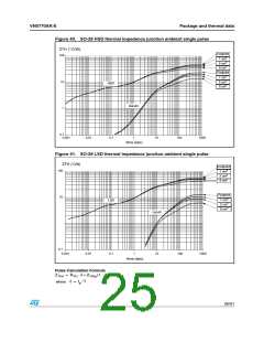
Table 20. Single pulse thermal impedance definitions
High Side Chip Thermal Impedance Junction to
Ambient
Z
Z
Z
Z
thHS
Low Side Chip Thermal Impedance Junction to
Ambient
= Z
= Z
thLS4
thLS
thLS3
Mutual Thermal Impedance Junction to Ambient
between High Side and Low Side Chips
= Z
= Z
thHS12LS4
thHSLS
thLSLS
thHS12LS3
thLS3LS4
Mutual Thermal Impedance Junction to Ambient
between Low Side Chips
= Z
1. values dependent on PCB heatsink area
(1)
Table 21. Thermal calculations in transient mode
TjHS12
TjLS3
TjLS4
Z
Z
x P
+ Z
x (P
+ P
) + T
dLS4 amb
thHS
dHS12
thHSLS
dLS3
x P
+ Z
x P
+ Z
x P
+ T
dLS4 amb
thHSLS
dHS12
thLS
dLS3
thLSLS
Z
x P
+ Z
x P
+ Z
x P
+ T
dLS4 amb
thHSLS
dHS12
thLSLS
dLS3
thLS
1. Calculation is valid in any dynamic operating condition. Pd values set by user.
24/31

 STMICROELECTRONICS [ ST ]