VIPER16
Automatic auto restart after overload or short-circuit
14
Automatic auto restart after overload or short-circuit
The overload protection is implemented in automatic way using the integrated up-down
counter. Every cycle, it is incremented or decremented depending if the current logic detects
the limit condition or not. The limit condition is the peak drain current, I
reported on
Dlim ,
Table 8 on page 7 or the one set by the user through the R
resistor, as reported in
LIM
Figure 13 on page 9. After the reset of the counter, if the peak drain current is continuously
equal to the level I , the counter will be incremented till the fixed time, t , after that will
Dlim
OVL
be disabled the power MOSFET switch ON. It will be activated again, through the soft start,
after the t time, see the Figure 25 and Figure 26 on page 17 and the mentioned time
RESTART
values on Table 8 on page 7.
In case of overload or short-circuit event, the power MOSFET switching will be stopped after
a time that depends from the counter and that can be as maximum equal to t
. The
OVL
protection will occur in the same way until the overload condition is removed, see Figure 25
and Figure 26 on page 17. This protection ensures restart attempts of the converter with low
repetition rate, so that it works safely with extremely low power throughput and avoiding the
IC overheating in case of repeated overload events. If the overload is removed before the
protection tripping, the counter will be decremented cycle by cycle down to zero and the IC
will not be stopped.
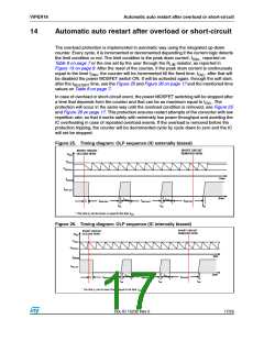
Figure 25. Timing diagram: OLP sequence (IC externally biased)
SHORT CIRCUIT
REMOVED HERE
SHORT CIRCUIT
OCCURS HERE
VDD
VDDon
VDDCSon
time
time
IDRAIN
IDlim_bm
tOVL
tOVL
*
tRESTART
t1
tRESTART
tRESTART
tSS
* The time t1 can be lower or equal to the time tOVL
tSS
tSS
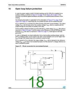
Figure 26. Timing diagram: OLP sequence (IC internally biased)
SHORT CIRCUIT
REMOVED HERE
SHORT CIRCUIT
OCCURS HERE
VDD
VDDon
VDDCSon
time
time
IDRAIN
IDlim_bm
tOVL
tOVL
*
tRESTART
t1
tRESTART
tRESTART
tSS
tSS
tSS
*
The time t1 can be lower than or equal to the time tOVL
Doc ID 15232 Rev 5
17/25

 STMICROELECTRONICS [ ST ]