VIPER16
Power section
7
Power section
The power section is implemented with an n-channel power MOSFET with a breakdown
voltage of 800 V min. and a typical R of 20 Ω. It includes a SenseFET structure to
DS(on)
allow a virtually lossless current sensing and the thermal sensor.
The gate driver of the power MOSFET is designed to supply a controlled gate current during
both turn-ON and turn-OFF in order to minimize common mode EMI. During UVLO
conditions, an internal pull-down circuit holds the gate low in order to ensure that the power
MOSFET cannot be turned ON accidentally.
8
High voltage current generator
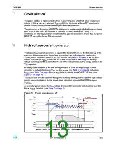
The high voltage current generator is supplied by the DRAIN pin. At the first start up of the
converter it is enabled when the voltage across the input bulk capacitor reaches the
V
threshold, sourcing a I
current (see Table 7 on page 6); as the V
DRAIN_START
DDch1 DD
voltage reaches the V
threshold, the power section starts switching and the high
DDon
voltage current generator is turned OFF. The VIPer16 is powered by the energy stored in the
capacitor.
V
DD
In steady state condition, if the self biasing function is used, the high voltage current
generator is activated between V and V (see Table 7 on page 6), delivering
DDCSon
DDon
I
, see Table 7 on page 6 to the V capacitor during the MOSFET off time (see
DDch2
DD
Figure 21 on page 13).
The device can also be supplied through the auxiliary winding; in this case the high voltage
current source is disabled during steady-state operation, provided that VDD is above
V
.
DDCSon
At converter power-down, the V voltage drops and the converter activity stops as it falls
DD
below V
threshold (see Table 7 on page 6).
DDoff
Figure 21. Power on and power off
VIN < VDRAIN_START
VIN
HV startup is no more activated
VDRAIN_START
With internal self-supply
VDD
t
regulation is lost here
Without internal self-supply
VDDon
VDDCSon
VDDoff
t
VDRAIN
IDD
IDDch2
t
t
IDDch1
Power-off
Normal operation
Power-on
Doc ID 15232 Rev 5
13/25

 STMICROELECTRONICS [ ST ]