VIPer12ADIP / VIPer12AS
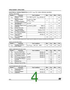
ELECTRICAL CHARACTERISTICS (Tj=25°C, VDD=18V, unless otherwise specified)
SUPPLY SECTION
Symbol
Parameter
Test Conditions
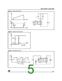
VDS=100V; V =5V ...V (See fig. 2)
DDon
Min.
Typ.
Max.
Unit
Start Up Charging
Current
I
-1
mA
DDch
DD
Start Up Charging
Current
in Thermal Shutdown
V
=5V; V =100V
DS
DD
I
0
mA
mA
DDoff
T > T - T
j
SD
HYST
Operating Supply Current
Not Switching
I
I
I
=2mA
3
5
DD0
FB
FB
Operating Supply Current
Switching
I
=0.5mA; I =50mA
(Note 1)
4.5
16
mA
%
V
DD1
D
D
Restart Duty Cycle
(See fig. 3)
RST
V
Undervoltage
DD
V
(See fig. 2 & 3)
(See fig. 2 & 3)
(See fig. 2)
7
8
9
DDoff
Shutdown Threshold
V
V
Start Up Threshold
13
5.8
14.5
6.5
16
7.2
V
DDon
DD
V
Threshold
DD
V
V
DDhyst
Hysteresis
Overvoltage
V
DD
V
38
42
46
V
DDovp
Threshold
Note: 1. These test conditions obtained with a resistive load are leading to the maximum conduction time of the device.
OSCILLATOR SECTION
Symbol
Parameter
Test Conditions
Min.
Typ.
Max.
Unit
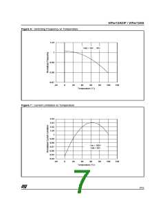
Oscillator Frequency
Total Variation
F
V
=V
... 35V; T=0 ... 100°C
54
60
66
kHz
OSC
DD
DDoff
j
PWM COMPARATOR SECTION
Symbol
Parameter
Test Conditions
Min.
Typ.
320
0.4
Max.
Unit
G
I
to I Current Gain
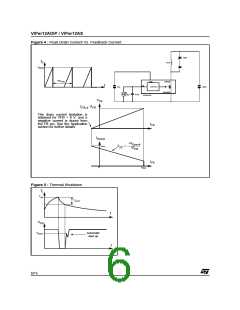
(See fig. 4)
ID
FB
D
I
V
=0V
FB
(See fig. 4)
Peak Current Limitation
I Shutdown Current
FB
0.32
0.48
A
Dlim
I
(See fig. 4)
(See fig. 4)
0.9
mA
kΩ
FBsd
R
I =0mA
FB Pin Input Impedance
1.2
FB
D
Current Sense Delay to
Turn-Off
t
I =0.2A
200
ns
d
D
t
Blanking Time
500
700
ns
ns
b
t
Minimum Turn On Time
ONmin
OVERTEMPERATURE SECTION
Symbol
Parameter
Test Conditions
Min.
Typ.
Max.
Unit
Thermal Shutdown
Temperature
T
(See fig. 5)
(See fig. 5)
140
170
°C
SD
Thermal Shutdown
Hysteresis
T
40
°C
HYST
4/15

 STMICROELECTRONICS [ ST ]