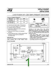
VIPer12ADIP / VIPer12AS
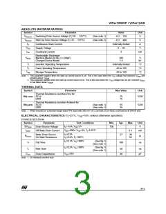
ABSOLUTE MAXIMUM RATINGS
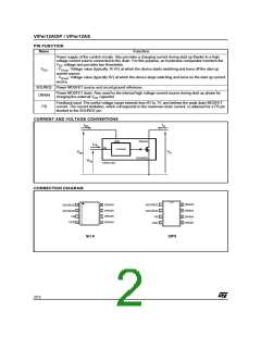
Symbol
Parameter
Value
-0.3 ... 730
-0.3 ... 400
Internally limited
0 ... 50
Unit
V
V
Switching Drain Source Voltage (T =25 ... 125°C)
(See note 1)
(See note 2)
DS(sw)
j
V
Start Up Drain Source Voltage (T =25 ... 125°C)
V
DS(st)
j
I
Continuous Drain Current
Supply Voltage
A
D
V
V
DD
I
Feedback Current
3
mA
FB
Electrostatic Discharge:
Machine Model (R=0Ω; C=200pF)
Charged Device Model
V
200
1.5
V
kV
ESD
T
Junction Operating Temperature
Case Operating Temperature
Storage Temperature
Internally limited
-40 to 150
°C
°C
°C
j
T
c
T
-55 to 150
stg
Note: 1. This parameter applies when the start up current source is off. This is the case when the V
voltage has reached V
and
DD
DDon
remains above V
.
DDoff
2. This parameter applies when the start up current source is on. This is the case when the V voltage has not yet reached V
DD
DDon
or has fallen below V
.
DDoff
THERMAL DATA
Symbol
Parameter
Max Value
Unit
Thermal Resistance Junction-Pins for:
Rthj-case SO-8
DIP8
25
15
°C/W
°C/W
Thermal Resistance Junction-Ambient for:
Rthj-amb SO-8
DIP8
(See note 1)
(See note 1)
55
45
Note: 1. When mounted on a standard single-sided FR4 board with 200 mm² of Cu (at least 35 µm thick) connected to all DRAIN pins.
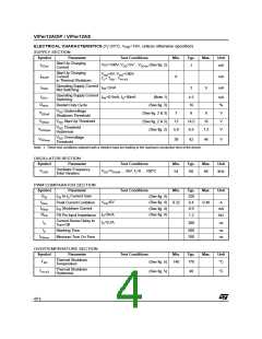
ELECTRICAL CHARACTERISTICS (Tj=25°C, VDD=18V, unless otherwise specified)
POWER SECTION
Symbol
Parameter
Test Conditions
I =1mA; V =2V
Min.
Typ.
Max.
Unit
V
BV
Drain-Source Voltage
Off State Drain Current
730
DSS
D
FB
I
V
=500V; V =2V; T=125°C
DS FB j
0.1
mA
DSS
I =0.2A
Static Drain-Source
On State Resistance
27
30
54
D
R
Ω
DSon
I =0.2A; T =100°C
D
j
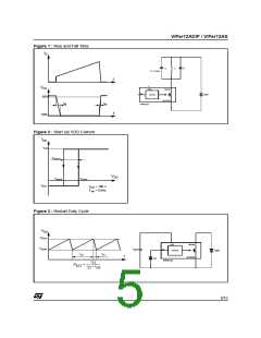
I =0.1A; V =300V
(See fig.1)
(See note 1)
D
IN
t
Fall Time
100
ns
f
I =0.2A; V =300V
(See fig.1)
(See note 1)
D
IN
t
Rise Time
50
40
ns
r
C
V
=25V
DS
Drain Capacitance
pF
oss
Note: 1. On clamped inductive load
3/15

 STMICROELECTRONICS [ ST ]