Description
TDA7719
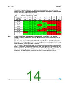
Since the input stage of this device has different configurations, the corresponding sources
for mixing selector are also different according to the configurations. The following table
defines the available sources for mixing under different configurations.
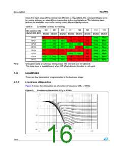
Table 8.
Available sources for mixing
000
001
010
011
100
101
110
111
Mix selector bits
(Byte2 Bit2~Bit0)
MixIN0 MixIN1 MixIN2 MixIN3 MixIN4 MixIN5 MixIN6 MixIN7
CFG0
CFG1
CFG2
CFG3
CFG4
CFG5
CFG6
CFG7
NA
NA
SE2
SE2
SE2
NA
NA
SE3
SE3
SE3
NA
NA
NA
NA
NA
NA
NA
NA
MD2
NA
NA
NA
NA
Beep
Beep
Beep
Beep
Beep
Beep
Beep
Beep
Mute
Mute
Mute
Mute
Mute
Mute
Mute
Mute
SE1
SE1
SE1
NA
SE4
MD1
NA
SE5
NA
NA
NA
NA
NA
SE4
NA
SE5
NA
MD3
SE1
SE2
SE2
SE3
SE3
NA
NA
Note:
Only green cells are allowed mixing input. The red cells are not allowed.
The beep input is available only when DC offset detector function is not used.
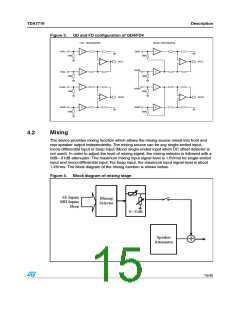
4.3
Loudness
There are four parameters programmable in the loudness stage:
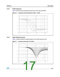
4.3.1
Loudness attenuation
Figure 5 shows the attenuation as a function of frequency at f = 400Hz
P
Figure 5.
Loudness attenuation @ f = 400Hz.
P
16/45

 STMICROELECTRONICS [ ST ]