TDA1675A
when a flyback pulse has been generated. If the
flyback pulse is absent (short cirucit or open cirucit
of the yoke), the blanking output remains high so
allowing the CRT protection.
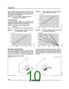
Figure 8 : Output Saturation Voltage to Supply
versus Output Peak Current
V1H (V)
2
Pin 13 is an open collector output where the
blanking pulse is available.
VS = 35V
1.5
Voltage regulator
The main supply voltage VS, is lowered and
regulated internally to allow the required reference
voltages for all the above described blocks.
1
Pin 14 is the main supply voltage input VS
IY (App)
1.5 2
(positive).
0.5
Pin 8
is the GND pin or the negative input of VS
0
0.5
1
Figure 7 : Output Saturation Voltage to Ground
Figure 9 : Maximum allowable Power Dissipation
vs. Peak Output Current
vs. Ambient Temperature
V1L (V)
1.5
Ptot (W)
32
I
R
th
N
VS = 35V
R
F
I
NI
t
h
=
=
24
16
8
4
/
2
˚
T
E
˚
C
C
/
W
1
/
W
Rt
HE
h
=
8
˚
A
T
C
W
S
I
N
K
0.5
IY (App)
Tamb (˚C)
50
0
-50
0
0.5
1
1.5
2
0
100
150
MOUNTING INSTRUCTIONS
spring (clip) being sufficient. Between the heatsink
and the package, it is better to insert a layer of
silicon grease, to optimize the thermal contact; no
electrical isolation is needed between the two
surfaces.
The power dissipated in the circuit must be
removed by adding an external heatsink. Thanks
to the MULTIWATT ® package attaching the
heatsink is very simple, a screw or a compression
Figure 10 : Mounting Examples
10/11

 STMICROELECTRONICS [ ST ]