Detailed Chipset Specifications
STV0681
7.8
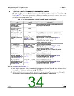
Typical current consumption of complete camera
The following data assumes that the camera has been built according to reference design referred
to in Chapter 10. Figures are approximate and depend on actual components sources - see notes.
The sensor operates at @ 3.3V DC
Table 14: Current consumption, complete STV0681+VV6411/6501 camera
Mode
Typical
Comments
’Snapshot’/Continuous/
Self timer mode
60mA
Assuming appropriate hardware included, power is sourced
from PC while USB connected.
(while un-tethered)
’Snapshot’/Continuous/
Self timer mode
(while tethered to PC)
60mA
90mA
While playing back audio
sounds through speaker
Assuming 8Ω speaker as explained in application note
AN1310
Standby mode
Approx. 270µA + SDRAM Total current in this mode equals:
self-refresh current
(when NOT connected to
USB)
STV0681 standby current consumption (see Note 1)
(see Note 2) + sensor
suspend mode current
+ SDRAM self-refresh current (see Note 2)
+ peripheral circuitry (approx. 50µA).
+ Sensor suspend mode current
PC Suspend mode
Approx. 300µA + SDRAM Total current in this mode equals:
self-refresh current
(when connected to USB):
Sensor SUSPEND pin
asserted
STV0681 Standby current consumption (see Note 1)
(see Note 2) + sensor
suspend mode current
+SDRAM self-refresh current (see Note 2)
+ peripheral circuitry (approx. 50µA)
+ 200µA, based on 1.5k pull-up in camera and 15k pull-
down in PC.
+ Sensor suspend mode current
Standby mode
Approx. 270µA + SDRAM Total current in this mode equals:
self-refresh current
(when not connected to
USB): sensor powered off
using FET (see Note 3)
STV0681 Standby current consumption (see Note 1)
(see Note 2)
+SDRAM self-refresh current (see Note 2)
+ peripheral circuitry (approx. 50µA).
PC Suspend mode
Approx. 100µA + SDRAM Total current in this mode equals:
self-refresh current
(when connected to USB):
sensor powered off using
FET (see Note 3)
STV0681 Standby current consumption (see Note 1)
(see Note 2)
+SDRAM self-refresh current (see Note 2)
+ peripheral circuitry (approx. 50µA).
Note: 1 See Table 9 from Section 7.3
2 From limited evaluation, typical self-refresh current figures of certain SDRAM chips are well below
manufacturers’ maximum specification, e.g. 100-250µA.
3 Option included in reference design to save current consumption, which can increase battery life
and increase chances of meeting USB suspend mode compliance requirements.
34/44
ADCS 7283313C

 STMICROELECTRONICS [ ST ]