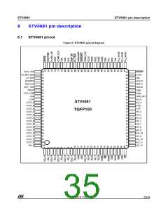
STV0681 pin description
STV0681
8.2
STV0681 pin description
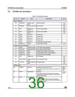
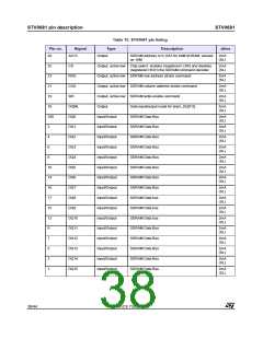
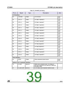
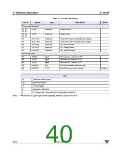
Table 15: STV0681 pin listing
Type Description
Pin no.
Signal
drive
Sensor Interface
65
64
56
57
SENSPWR
Output, active
high
Power-up Sensor
2mA
(SL)
SENSRST
SCL
Output, active low Reset Sensor
2mA
(SL)
Input/Output
(OD,T)
Sensor serial interface
4mA
(SL)
SDA
Input/Output
(OD,T)
Sensor serial interface
4mA
(SL)
58
59
60
61
62
63
SD[3]
Input (S,T)
Input (S,T)
Input (S,T)
Input (S,T)
Input (S,T)
Output
Sensor data
SD[2]
Sensor data
SD[1]
Sensor data
SD[0]
Sensor data
QCLK
Qualification clock from sensor
Clock output to sensor
SENS_CLK
4mA
I/O and Camera Control pins
75
74
73
72
71
68
MODE
Debounced input
Debounced input
Input
Push button (Wake-up/Mode)
Push button (Shutter/Confirm)
Enable Flash Exposure (Active High)
S elect between 50Hz and 60Hz lighting
Output from Audio Comparator
LED indicator
SHUTTER
FLASH_EN
50/60_SEL
COMP_OUT
LED
Input
Input
Output (OD)
8mA
(SL)
67
66
AMP_ENABLE Output, active low
(OD)
Audio Amplifier Enable
Flashgun trigger
8mA
(SL)
FL_TRIG
Output, active low
(OD)
8mA
(SL)
USB Interface
42
USBDET
Input (S)
Detect Power source from USB.
USB
specific
ation
V1.1
(For camera with RS232 only, this pin should be tied
to GND)
43
DATA+
DATA-
Input/Output
USB bus
complia
nt I/O
(For camera with RS232 only, this pin should be
connected to test points to allow for USB production
test (lens focussing))
44
Input/Output
USB bus.
(For camera with RS232 only, this pin should be
connected to test points to allow for USB production
test (lens focussing))
36/44
ADCS 7283313C

 STMICROELECTRONICS [ ST ]