STTH1212
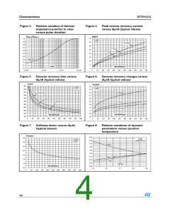
Figure 9.
Characteristics
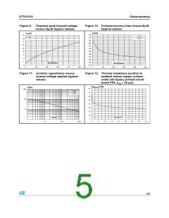
Transient peak forward voltage
versus dIF/dt (typical values)
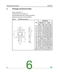
Figure 10. Forward recovery time versus dIF/dt
(typical values)
t (ns)
fr
V
(V)
FP
750
700
650
600
550
500
450
400
350
300
250
200
45
40
35
30
25
20
15
10
5
IF=IF(AV)
VFR=1.5 x VF max.
Tj=125°C
IF=IF(AV)
Tj=125°C
dI /dt(A/µs)
F
dI /dt(A/µs)
F
0
0
100
200
300
400
500
0
100
200
300
400
500
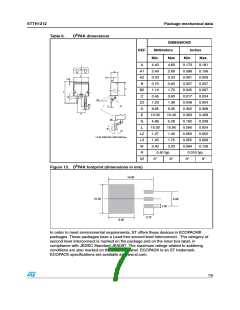
Figure 11. Junction capacitance versus
reverse voltage applied (typical
values)
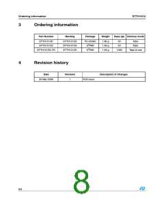
Figure 12. Thermal resistance junction to
ambient versus copper surface
under tab (Epoxy printed circuit
board FR4, ecu = 35 µm)
R (°C/W)
th(j-a)
C(pF)
80
70
60
50
40
30
20
10
0
1000
F=1MHz
VOSC=30mVRMS
Tj=25°C
100
10
SCU(cm²)
V (V)
R
1
0
5
10
15
20
25
30
35
40
1
10
100
1000
5/9

 STMICROELECTRONICS [ ST ]