STM32F302xx/STM32F303xx
Electrical characteristics
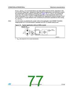
For C and C , it is recommended to use high-quality external ceramic capacitors in the
L1
L2
5 pF to 25 pF range (typ.), designed for high-frequency applications, and selected to match
the requirements of the crystal or resonator (see Figure 16). C and C are usually the
L1
L2
same size. The crystal manufacturer typically specifies a load capacitance which is the
series combination of C and C . PCB and MCU pin capacitance must be included (10 pF
L1
L2
can be used as a rough estimate of the combined pin and board capacitance) when sizing
and C .
C
L1
L2
Note:
For information on selecting the crystal, refer to the application note AN2867 “Oscillator
design guide for ST microcontrollers” available from the ST website www.st.com.
Figure 16. Typical application with an 8 MHz crystal
2ESONATOR WITH
INTEGRATED CAPACITORS
#
,ꢃ
F
/3#?).
(3%
"IAS
CONTROLLED
GAIN
ꢁ -(Z
RESONATOR
2
&
/3#?/54
ꢐꢃꢑ
2
%84
#
,ꢉ
-3ꢃꢅꢁꢆꢂ6ꢃ
1. REXT value depends on the crystal characteristics.
Doc ID 023353 Rev 5
77/133

 STMICROELECTRONICS [ ST ]