STA335BW
Register description
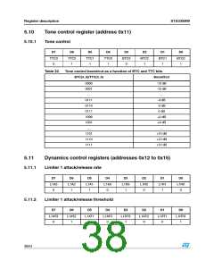
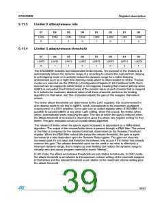
5.11.3
Limiter 2 attack/release rate
D7
D6
D5
D4
D3
D2
D1
D0
L2A3
0
L2A2
1
L2A1
1
L2A0
0
L2R3
1
L2R2
0
L2R1
1
L2R0
0
5.11.4
Limiter 2 attack/release threshold
D7
D6
D5
D4
D3
D2
D1
D0
L2AT3
0
L2AT2
1
L2AT1
1
L2AT0
0
L2RT3
1
L2RT2
0
L2RT1
0
L2RT0
1
The STA335BW includes two independent limiter blocks. The purpose of the limiters is to
automatically reduce the dynamic range of a recording to prevent the outputs from clipping
in anti-clipping mode or to actively reduce the dynamic range for a better listening
environment such as a night-time listening mode which is often needed for DVDs. The two
modes are selected via the DRC bit in Configuration Register F, bit 0 address 0x05. Each
channel can be mapped to either limiter or not mapped, meaning that channel will clip when
0dBFS is exceeded. Each limiter looks at the present value of each channel that is mapped
to it, selects the maximum absolute value of all these channels, performs the limiting
algorithm on that value, and then if needed adjusts the gain of the mapped channels in
unison.
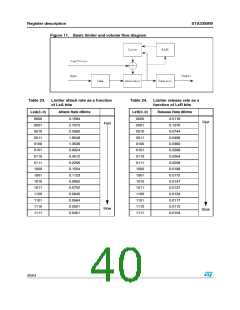
The limiter attack thresholds are determined by the LxAT registers. It is recommended in
anti-clipping mode to set this to 0dBFS, which corresponds to the maximum unclipped
output power of a DDX amplifier. Since gain can be added digitally within STA559BW it is
possible to exceed 0dBFS or any other LxAT setting, when this occurs, the limiter, when
active, automatically starts reducing the gain. The rate at which the gain is reduced when
the attack threshold is exceeded is dependent upon the attack rate register setting for that
limiter. The gain reduction occurs on a peak-detect algorithm.
The release of limiter, when the gain is again increased, is dependent on a RMS-detect
algorithm. The output of the volume/limiter block is passed through a RMS filter. The output
of this filter is compared to the release threshold, determined by the Release Threshold
register. When the RMS filter output falls below the release threshold, the gain is again
increased at a rate dependent upon the Release Rate register. The gain can never be
increased past it's set value and therefore the release only occurs if the limiter has already
reduced the gain. The release threshold value can be used to set what is effectively a
minimum dynamic range, this is helpful as over-limiting can reduce the dynamic range to
virtually zero and cause program material to sound “lifeless”.
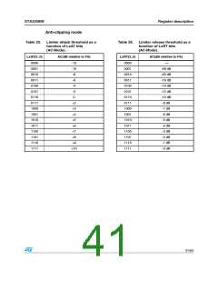
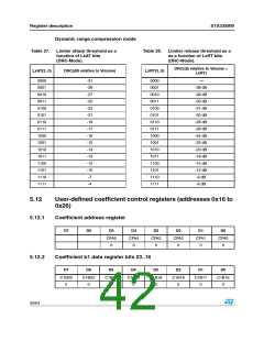
In AC mode, the attack and release thresholds are set relative to full-scale. In DRC mode,
the attack threshold is set relative to the maximum volume setting of the channels mapped
to that limiter and the release threshold is set relative to the maximum volume setting plus
the attack threshold.
39/54

 STMICROELECTRONICS [ ST ]