STA335BW
Register description
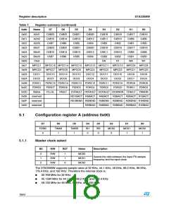
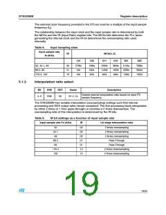
The external clock frequency provided to the XTI pin must be a multiple of the input sample
frequency (f ).
s
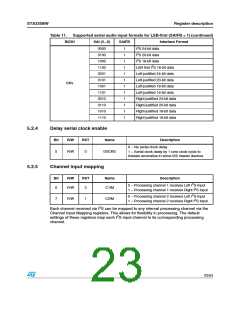
The relationship between the input clock and the input sample rate is determined by both
the MCSx and the IR (Input Rate) register bits. The MCSx bits determine the PLL factor
generating the internal clock and the IR bit determines the oversampling ratio used
internally
Table 8.
Input sample rate
fs (KHz)
Input sampling rates
IR
MCS(2..0)
101
100
011
010
001
000
32, 44.1, 48
88.2, 96
00
01
1X
576fs
NA
128fs
64fs
32fs
256fs
128fs
64fs
384fs
192fs
96fs
512fs
256fs
128fs
768fs
384fs
192fs
176.4, 192
NA
5.1.2
Interpolation ratio select
Bit
R/W
RST
Name
IR (1..0)
Description
Selects internal interpolation ratio based on input I2S
sample frequency
4..3
R/W
00
The STA335BW has variable interpolation (oversampling) settings such that internal
processing and DDX output rates remain consistent. The first processing block interpolates
by either 2 times or 1 time (pass-through) or provides a 2 times downsample. The
oversampling ratio of this interpolation is determined by the IR bits.
Table 9.
IR bit settings as a function of input sample rate
Input sample rate Fs (KHz)
IR
1st stage interpolation ratio
32
44.1
48
00
00
00
01
01
10
10
2 times oversampling
2 times oversampling
2 times oversampling
Pass-Through
88.2
96
Pass-Through
176.4
192
2 times downsampling
2 times downsampling
19/54

 STMICROELECTRONICS [ ST ]