STA335BW
Electrical specifications
3.4
Testing
3.4.1
Functional pin status
Table 6.
Functional pin status
Pin name
Pin #
Logicvalue
IC-STATUS
PWRDN
PWRDN
23
23
0
1
Low Absorption
Normal Operation
From external power stage is indicated a Temperature
Warning.
TWARN
TWARN
EAPD
20
20
19
19
0
1
0
1
Normal Operation
Low Absorption for power stage. All internal regulators are
switched off.
EAPD
Normal operation
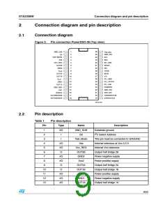
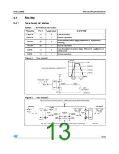
Figure 3.
Test circuit 1
OUTxY
Vcc
(3/4)Vcc
Low current dead time = MAX(DTr,DTf)
(1/2)Vcc
(1/4)Vcc
+Vcc
t
DTr
DTf
Duty cycle = 50%
INxY
M58
M57
OUTxY
R 8Ω
+
-
V67 =
vdc = Vcc/2
gnd
D03AU1458
Figure 4.
Test circuit 2
High Current Dead time for Bridge application = ABS(DTout(A)-DTin(A))+ABS(DTOUT(B)-DTin(B))
+VCC
Duty cycle=A
Duty cycle=B
DTout(A)
M58
M57
M64
M63
Q1
OUTA
Iout=1.5A
Q2
OUTB
Iout=1.5A
DTin(A)
INA
DTout(B)
L68 10µ
DTin(B)
INB
Rload=4Ω
L67 10µ
Q3
C69
470nF
C70
470nF
Q4
C71 470nF
Duty cycle A and B: Fixed to have DC output current of 4A in the direction shown in figure
D06AU1651
13/54

 STMICROELECTRONICS [ ST ]