STA326
7.12.2 Limiter 1 Attack/Release Threshold (Address 13h)
D7
L1AT3
0
D6
L1AT2
1
D5
L1AT1
1
D4
L1AT0
0
D3
L1RT3
1
D2
L1RT2
0
D1
L1RT1
0
D0
L1RT0
1
7.12.3 Limiter 2 Attack/Release Rate (Address 14h)
D7
L2A3
0
D6
L2A2
1
D5
L2A1
1
D4
L2A0
0
D3
L2R3
1
D2
L2R2
0
D1
L2R1
1
D0
L2R0
0
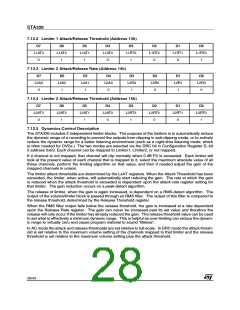
7.12.4 Limiter 2 Attack/Release Threshold (Address 15h)
D7
L2AT3
0
D6
L2AT2
1
D5
L2AT1
1
D4
L2AT0
0
D3
L2RT3
1
D2
L2RT2
0
D1
L2RT1
0
D0
L2RT0
1
7.12.5 Dynamics Control Description
The STA326 includes 2 independent limiter blocks. The purpose of the limiters is to automatically reduce
the dynamic range of a recording to prevent the outputs from clipping in anti-clipping mode, or to actively
reduce the dynamic range for a better listening environment (such as a night-time listening mode, which
is often needed for DVDs.) The two modes are selected via the DRC bit in Configuration Register D, bit
5 address 0x03. Each channel can be mapped to Limiter1, Limiter2, or not mapped.
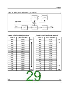
If a channel is not mapped, that channel will clip normally when 0 dB FS is exceeded. Each limiter will
look at the present value of each channel that is mapped to it, select the maximum absolute value of all
these channels, perform the limiting algorithm on that value, and then if needed adjust the gain of the
mapped channels in unison.
The limiter attack thresholds are determined by the LxAT registers. When the Attack Thesehold has been
exceeded, the limiter, when active, will automatically start reducing the gain. The rate at which the gain
is reduced when the attack threshold is exceeded is dependent upon the attack rate register setting for
that limiter. The gain reduction occurs on a peak-detect algorithm.
The release of limiter, when the gain is again increased, is dependent on a RMS-detect algorithm. The
output of the volume/limiter block is passed through an RMS filter. The output of this filter is compared to
the release threshold, determined by the Release Threshold register.
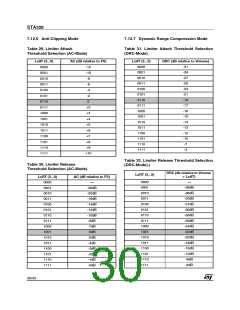
When the RMS filter output falls below the release threshold, the gain is increased at a rate dependent
upon the Release Rate register. The gain can never be increased past its set value and therefore the
release will only occur if the limiter has already reduced the gain. The release threshold value can be used
to set what is effectively a minimum dynamic range. This is helpful as over-limiting can reduce the dynam-
ic range to virtually zero and cause program material to sound “lifeless”.
In AC mode the attack and release thresholds are set relative to full-scale. In DRC mode the attack thresh-
old is set relative to the maximum volume setting of the channels mapped to that limiter and the release
threshold is set relative to the maximum volume setting plus the attack threshold.
28/43

 STMICROELECTRONICS [ ST ]