STA326
7.10 Channel Configuration Registers
7.10.1 Channel 1 Configuration (Address 0Eh)
D7
C1OM1
0
D6
C1OM0
0
D5
C1LS1
0
D4
C1LS0
0
D3
C1BO
0
D2
C1VBP
0
D1
C1EQBP
0
D0
C1TCB
0
7.10.2 Channel 2 Configuration (Address 0Fh)
D7
C2OM1
0
D6
C2OM0
0
D5
C2LS1
0
D4
C2LS0
0
D3
C2BO
0
D2
C2VBP
0
D1
C2EQBP
0
D0
C2TCB
0
7.10.3 Channel 3 Configuration (Address 10h)
D7
C3OM1
0
D6
C3OM0
0
D5
C3LS1
0
D4
C3LS0
0
D3
C3BO
0
D2
C3VBP
0
D1
D0
EQ control can be bypassed on a per channel basis. If EQ control is bypassed on a given channel the
prescale and all 9 filters (high-pass, biquads, de-emphasis, bass management cross-over, bass, treble in
any combination) are bypassed for that channel.
CxEQBP:
– 0 Perform EQ on Channel X – normal operation
– 1 Bypass EQ on Channel X
Tone control (bass/treble) can be bypassed on a per channel basis. If tone control is bypassed on a given
channel the two filters that tone control utilizes are bypassed.
CxTCB:
– 0 Perform Tone Control on Channel x – (default operation)
– 1 Bypass Tone Control on Channel x
Each channel can be configured to output either the patented DDX PWM data or standart binary PWM
encoded data. By setting the CxBO bit to ‘1’, each channel can be individually controlled to be in binary
operation mode.
Also, there is the capability to map each channel independently onto any of the two limiters available within
the STA326 or even not map it to any limiter at all (default mode).
Table 24. Channel Limiter Mapping Selection
CxLS (1,0)
Channel Limiter Mapping
Channel has limiting disabled
00
01
10
Channel is mapped to limiter #1
Channel is mapped to limiter #2
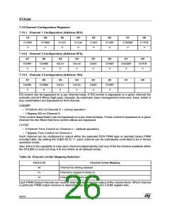
Each PWM Output Channel can receive data from any channel output of the volume block. Which channel
a particular PWM output receives is dependent upon that channel’s CxOM register bits.
26/43

 STMICROELECTRONICS [ ST ]