STA326
7.9.3 Register – AutoMode AM/Pre-Scale/Bass Management Scale (Address 0Ch)
D7
XO3
0
D6
XO2
0
D5
XO1
0
D4
XO0
0
D3
AMAM2
0
D2
AMAM1
0
D1
AMAM0
0
D0
AMAME
0
7.9.3.1AutoMode AM Switching Enable
BIT
R/W
RST
NAME
DESCRIPTION
0
R/W
0
AMAME
AutoMode AM Enable
0 – Switching Frequency Determined by PWMS Setting
1 – Switching Frequency Determined by AMAM Settings
3…1
R/W
000
AMAM (2…0)
AM Switching Frequency Setting
Default: 000
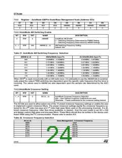
Table 21. AutoMode AM Switching Frequency Selection
AMAM (2..0)
000
48kHz/96kHz Input Fs
0.535MHz – 0.720MHz
0.721MHz – 0.900MHz
0.901MHz – 1.100MHz
1.101MHz – 1.300MHz
1.301MHz – 1.480MHz
1.481MHz – 1.600MHz
1.601MHz – 1.700MHz
44.1kHz/88.2kHz Input Fs
0.535MHz – 0.670Mhz
0.671MHz – 0.800MHz
0.801MHz – 1.000MHz
1.001MHz – 1.180MHz
1.181MHz – 1.340Mhz
1.341MHz – 1.500MHz
1.501MHz – 1.700MHz
001
010
011
100
101
110
When DDX® is used concurrently with an AM radio tuner, it is advisable to use the AMAM bits to automat-
ically adjust the output PWM switching rate dependent upon the specific radio frequency that the tuner is
receiving. The values used in AMAM are also dependent upon the sample rate determined by the ADC
used.
7.9.3.2AutoMode Crossover Setting
BIT
R/W
RST
NAME
DESCRIPTION
7…4
R/W
0
XO (3…0)
AutoMode Crossover Frequency Selection
000 – User Defined Crossover coefficients are used
Otherwise – Preset coefficients for the crossover setting desired
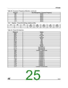
The XO bits are used to either select one of the 15 preset crossover frequency settings or enable the user
to implement custom crossover filters. The preset crossover settings signify the crossover frequency se-
lected for the 2nd order low pass and 1st order high pass filters used on the processing channels. If a dif-
ferent crossover frequency, other than those available, is desired, then the user needs to set XO = 000
and design custom high-pass and low-pass filters. These filters should then be written to the device coef-
ficient RAM using the I2C communication. Please refer to section 8.6.
Table 22. Crossover Frequency Selection
XO (2..0)
0000
0001
0010
0011
0100
0101
0110
0111
Bass Management - Crossover Frequency
User
80 Hz
100 Hz
120 Hz
140 Hz
160 Hz
180 Hz
200 Hz
24/43

 STMICROELECTRONICS [ ST ]