EXTENDED FUNCTION TIMER (EFT)
EXTENDED FUNCTION TIMER (Cont’d)
10.3.4 Interrupt Management
– Set the OCIE (or OC1IE/OC2IE bits) and/or ICIE
(or IC1IE/IC2IE bits and/or TOIE bit(s) in the CR1
register to enable interrupts
The interrupts of the Extended Function Timer are
mapped on one of the eight External Interrupt
Channels of the microcontroller (refer to the “Inter-
rupts” chapter).
The three interrupt sources are mapped on the
same interrupt channel. To use them, the EFTIS
bit must be set)
– In the EIPR register, reset the pending bit of the
interrupt channel used by the peripheral inter-
rupts to avoid any spurious interrupt requests be-
ing performed when the mask bit is set
– Set the mask bits of the interrupt channels used
to enable the MCU to acknowledge the interrupt
requests of the peripheral.
Each External Interrupt Channel has:
– A trigger control bit in the EITR register (R242 -
Page 0),
– Clear all EFT interrupt flags by reading the Sta-
tus, Input Capture Low, Output Compare Low
and Counter Low Registers.
– A pending bit in the EIPR register (R243 - Page
0),
Caution:
– A mask bit in the EIMR register (R244 - Page 0).
1. It is mandatory to clear all EFT interrupt flags
simultaneously at least once before exiting an
EFT timer interrupt routine (the SR register
must = 00h at some point during the interrupt
routine), otherwise no interrupts can be issued
on that channel anymore.
Program the interrupt priority level using the EI-
PLR register (R245 - Page 0). For a description of
these registers refer to the “Interrupts” and “DMA”
chapters.
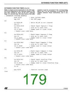
Refer to the following assembly code for an
interrupt sequence example.
Using the external interrupt channel for all EFT
interrupts
To use the interrupt features, perform the following
sequence:
2. Since a loop statement is needed inside the IT
routine, the user must avoid situations where
an interrupt event period is narrower than the
duration of the interrupt treatment. Otherwise
nested interrupt mode must be used to serve
higher priority requests.
– Set the priority level of the interrupt channel used
(EIPLR register)
– Select the interrupt trigger edge as rising edge
(set the corresponding bit in the EITR register)
– Set the EFTIS bit of the CR3 register to select
the peripheral interrupt sources
178/426
9

 STMICROELECTRONICS [ ST ]