ST24E16, ST25E16
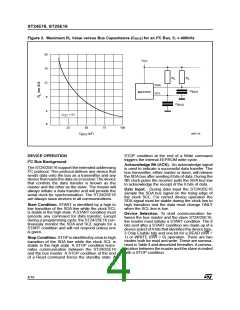
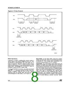
Figure 6. I2C Bus Protocol
SCL
SDA
START
SDA
SDA
STOP
CONDITION
INPUT CHANGE
CONDITION
1
2
3
7
8
9
SCL
SDA
ACK
MSB
START
CONDITION
1
2
3
7
8
9
SCL
SDA
MSB
ACK
STOP
CONDITION
AI00792
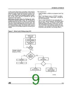
Write Operations
Byte Write. In the Byte Write mode the master
sends one data byte, which isacknowledged by the
ST24/25E16. The master then terminates the
transfer by generating a STOP condition.
Following a START condition the master sends a
device select code with the RW bit reset to ’0’. The
ST24/25E16 acknowledge this and waits for 2
bytes of address. These 2 address bytes (8 bits
each) provide access to any of the 8 blocks of 256
bytes each. Writing in the ST24/25E16 may be
inhibited if input pin WC is taken high.
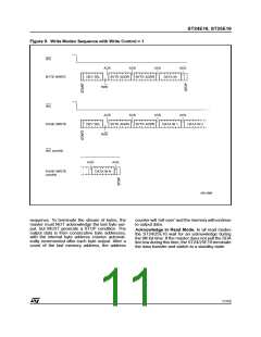
Page Write. The Page Write mode allows up to 16
bytes to be written in a single write cycle, provided
that they are all located in the same row of 16 bytes
in the memory, that is the same Address bits (b10-
b4). The master sends one up to 16 bytes of data,
which are each acknowledged by the ST24/25E16.
After each byte is transfered, the internal byte
address counter (4 Least Significant Bits only) is
incremented. The transfer is terminated by the
master generating a STOPcondition. Care must be
taken to avoid address counter ’roll-over’ which
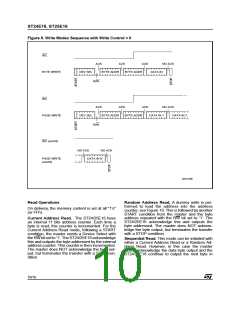
For the ST24/25E16 versions, any write command
with WC = ’1’ (during a period of time from the
START condition untill the end of the 2 Bytes
Address) will not modify data and will NOT be
acknowledged on data bytes, as in Figure 9.
8/16

 STMICROELECTRONICS [ ST ]