ST10F276E
Interrupt system
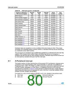
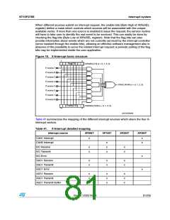
When different sources submit an interrupt request, the enable bits (Byte High of XIRxSEL
register) define a mask which controls which sources will be associated with the unique
available vector. If more than one source is enabled to issue the request, the service routine
will have to take care to identify the real event to be serviced. This can easily be done by
checking the flag bits (Byte Low of XIRxSEL register). Note that the flag bits can also
provide information about events which are not currently serviced by the interrupt controller
(since masked through the enable bits), allowing an effective software management also in
absence of the possibility to serve the related interrupt request: a periodic polling of the flag
bits may be implemented inside the user application.
Figure 16. X-Interrupt basic structure
ꢊ
ꢉ
&LAG;ꢊꢐꢉ=
8)2X3%,;ꢊꢐꢉ= ꢍX ꢓ ꢉꢗ ꢀꢗ ꢁꢗ ꢈꢏ
)4 SOURCE ꢊ
)4 SOURCE ꢄ
)4 SOURCE ꢃ
)4 SOURCE ꢇ
)4 SOURCE ꢈ
)4 SOURCE ꢁ
)4 SOURCE ꢀ
)4 SOURCE ꢉ
80X)#ꢌ80X)2 ꢍX ꢓ ꢉꢗ ꢀꢗ ꢁꢗ ꢈꢏ
%NABLE;ꢊꢐꢉ=
8)2X3%,;ꢀꢃꢐꢆ= ꢍX ꢓ ꢉꢗ ꢀꢗ ꢁꢗ ꢈꢏ
ꢀꢃ
ꢆ
'!0'2)ꢉꢉꢉꢋꢈ
Table 41 summarizes the mapping of the different interrupt sources which share the four X-
interrupt vectors.
Table 41. X-Interrupt detailed mapping
Interrupt source
CAN1 Interrupt
XP0INT
XP1INT
XP2INT
XP3INT
x
x
x
CAN2 Interrupt
I2C Receive
x
x
x
x
x
x
x
I2C Transmit
I2C Error
x
x
SSC1 Receive
SSC1 Transmit
SSC1 Error
x
x
x
x
x
x
ASC1 Receive
ASC1 Transmit
ASC1 Transmit Buffer
x
x
x
x
x
x
x
x
x
Doc ID 12303 Rev 3
81/235

 STMICROELECTRONICS [ ST ]