Interrupt system
ST10F276E
8
Interrupt system
The interrupt response time for internal program execution is from 78ns to 187.5ns at
64 MHz CPU clock.
The ST10F276E architecture supports several mechanisms for fast and flexible response to
service requests that can be generated from various sources (internal or external) to the
microcontroller. Any of these interrupt requests can be serviced by the Interrupt Controller or
by the Peripheral Event Controller (PEC).
In contrast to a standard interrupt service where the current program execution is
suspended and a branch to the interrupt vector table is performed, just one cycle is ‘stolen’
from the current CPU activity to perform a PEC service. A PEC service implies a single Byte
or Word data transfer between any two memory locations with an additional increment of
either the PEC source or destination pointer. An individual PEC transfer counter is implicitly
decremented for each PEC service except when performing in the continuous transfer
mode. When this counter reaches zero, a standard interrupt is performed to the
corresponding source related vector location. PEC services are very well suited to perform
the transmission or the reception of blocks of data. The ST10F276E has 8 PEC channels,
each of them offers such fast interrupt-driven data transfer capabilities.
An interrupt control register which contains an interrupt request flag, an interrupt enable flag
and an interrupt priority bit-field is dedicated to each existing interrupt source. Thanks to its
related register, each source can be programmed to one of sixteen interrupt priority levels.
Once starting to be processed by the CPU, an interrupt service can only be interrupted by a
higher prioritized service request. For the standard interrupt processing, each of the
possible interrupt sources has a dedicated vector location.
Software interrupts are supported by means of the ‘TRAP’ instruction in combination with an
individual trap (interrupt) number.
Fast external interrupt inputs are provided to service external interrupts with high precision
requirements. These fast interrupt inputs feature programmable edge detection (rising edge,
falling edge or both edges).
Fast external interrupts may also have interrupt sources selected from other peripherals; for
example the CANx controller receive signals (CANx_RxD) and I2C serial clock signal can be
used to interrupt the system.
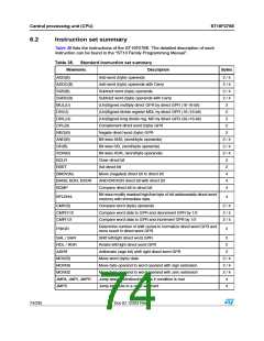
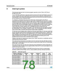
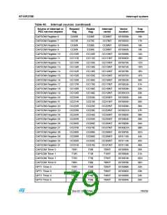
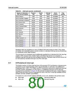
Table 40 shows all the available ST10F276E interrupt sources and the corresponding
hardware-related interrupt flags, vectors, vector locations and trap (interrupt) numbers:
Table 40. Interrupt sources
Source of interrupt or
PEC service request
Request
flag
Enable
flag
Interrupt
vector
Vector
location
Trap
number
CAPCOM Register 0
CAPCOM Register 1
CAPCOM Register 2
CAPCOM Register 3
CAPCOM Register 4
CAPCOM Register 5
CC0IR
CC1IR
CC2IR
CC3IR
CC4IR
CC5IR
CC0IE
CC1IE
CC2IE
CC3IE
CC4IE
CC5IE
CC0INT
CC1INT
CC2INT
CC3INT
CC4INT
CC5INT
00’0040h
00’0044h
00’0048h
00’004Ch
00’0050h
00’0054h
10h
11h
12h
13h
14h
15h
78/235
Doc ID 12303 Rev 3

 STMICROELECTRONICS [ ST ]