ST10F276E
General purpose timer unit
10
General purpose timer unit
The GPT unit is a flexible multifunctional timer/counter structure which is used for time
related tasks such as event timing and counting, pulse width and duty cycle measurements,
pulse generation, or pulse multiplication. The GPT unit contains five 16-bit timers organized
into two separate modules GPT1 and GPT2. Each timer in each module may operate
independently in several different modes, or may be concatenated with another timer of the
same module.
10.1
GPT1
Each of the three timers T2, T3, T4 of the GPT1 module can be configured individually for
one of four basic modes of operation: timer, gated timer, counter mode and incremental
interface mode.
In timer mode, the input clock for a timer is derived from the CPU clock, divided by a
programmable prescaler.
In counter mode, the timer is clocked in reference to external events.
Pulse width or duty cycle measurement is supported in gated timer mode where the
operation of a timer is controlled by the ‘gate’ level on an external input pin. For these
purposes, each timer has one associated port pin (TxIN) which serves as gate or clock
input.
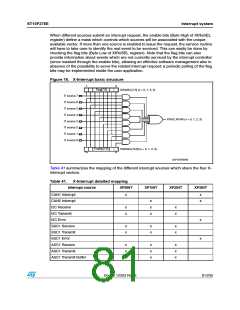
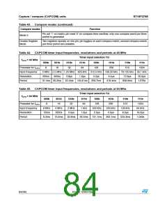
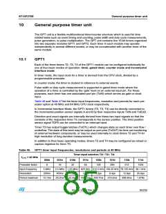
Table 46 and Table 47 list the timer input frequencies, resolution and periods for each pre-
scaler option at 40 MHz and 64 MHz CPU clock respectively.
In Incremental Interface Mode, the GPT1 timers (T2, T3, T4) can be directly connected to
the incremental position sensor signals A and B by their respective inputs TxIN and TxEUD.
Direction and count signals are internally derived from these two input signals so that the
contents of the respective timer Tx corresponds to the sensor position. The third position
sensor signal TOP0 can be connected to an interrupt input.
Timer T3 has output toggle latches (TxOTL) which changes state on each timer over flow /
underflow. The state of this latch may be output on port pins (TxOUT) for time out monitoring
of external hardware components, or may be used internally to clock timers T2 and T4 for
high resolution of long duration measurements.
In addition to their basic operating modes, timers T2 and T4 may be configured as reload or
capture registers for timer T3.
Table 46. GPT1 timer input frequencies, resolutions and periods at 40 MHz
Timer input selection T2I / T3I / T4I
fCPU = 40 MHz
000b
001b
010b
011b
100b
101b
110b
111b
Prescaler factor
Input frequency
Resolution
8
16
32
64
128
256
512
1024
5 MHz
200ns
13.1ms
2.5 MHz 1.25 MHz 625 kHz 312.5 kHz 156.25 kHz 78.125 kHz 39.1 kHz
400ns
0.8µs
1.6µs
3.2µs
6.4µs
12.8µs
25.6µs
1.678s
Period maximum
26.2ms
52.4ms 104.8 ms 209.7ms
419.4ms
838.9ms
Doc ID 12303 Rev 3
85/235

 STMICROELECTRONICS [ ST ]