Interrupt system
ST10F276E
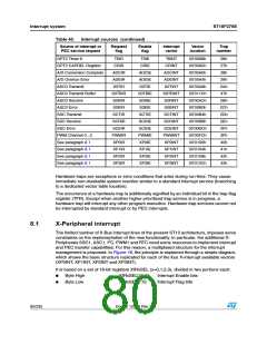
Table 40. Interrupt sources (continued)
Source of interrupt or
PEC service request
Request
flag
Enable
flag
Interrupt
vector
Vector
location
Trap
number
GPT2 Timer 6
T6IR
CRIR
T6IE
CRIE
T6INT
CRINT
00’0098h
00’009Ch
00’00A0h
00’00A4h
00’00A8h
00’011Ch
00’00ACh
00’00B0h
00’00B4h
00’00B8h
00’00BCh
00’00FCh
00’0100h
00’0104h
00’0108h
00’010Ch
26h
27h
28h
29h
2Ah
47h
2Bh
2Ch
2Dh
2Eh
2Fh
3Fh
40h
41h
42h
43h
GPT2 CAPREL Register
A/D Conversion Complete
A/D Overrun Error
ASC0 Transmit
ADCIR
ADEIR
S0TIR
S0TBIR
S0RIR
S0EIR
SCTIR
SCRIR
SCEIR
PWMIR
XP0IR
XP1IR
XP2IR
XP3IR
ADCIE
ADEIE
S0TIE
S0TBIE
S0RIE
S0EIE
SCTIE
SCRIE
SCEIE
PWMIE
XP0IE
XP1IE
XP2IE
XP3IE
ADCINT
ADEINT
S0TINT
S0TBINT
S0RINT
S0EINT
SCTINT
SCRINT
SCEINT
PWMINT
XP0INT
XP1INT
XP2INT
XP3INT
ASC0 Transmit Buffer
ASC0 Receive
ASC0 Error
SSC Transmit
SSC Receive
SSC Error
PWM Channel 0...3
See paragraph 8.1
See paragraph 8.1
See paragraph 8.1
See paragraph 8.1
Hardware traps are exceptions or error conditions that arise during run-time. They cause
immediate non-maskable system reaction similar to a standard interrupt service (branching
to a dedicated vector table location).
The occurrence of a hardware trap is additionally signified by an individual bit in the trap flag
register (TFR). Except when another higher prioritized trap service is in progress, a
hardware trap will interrupt any other program execution. Hardware trap services cannot not
be interrupted by standard interrupt or by PEC interrupts.
8.1
X-Peripheral interrupt
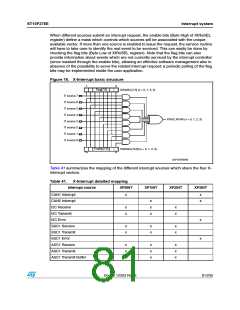
The limited number of X-Bus interrupt lines of the present ST10 architecture, imposes some
constraints on the implementation of the new functionality. In particular, the additional X-
Peripherals SSC1, ASC1, I2C, PWM1 and RTC need some resources to implement interrupt
and PEC transfer capabilities. For this reason, a multiplexed structure for the interrupt
management is proposed. In Figure 16, the principle is explained through a simple diagram,
which shows the basic structure replicated for each of the four X-interrupt available vectors
(XP0INT, XP1INT, XP2INT and XP3INT).
It is based on a set of 16-bit registers XIRxSEL (x=0,1,2,3), divided in two portions each:
●
Byte High
Byte Low
XIRxSEL[15:8]
XIRxSEL[7:0]
Interrupt Enable bits
Interrupt Flag bits
●
80/235
Doc ID 12303 Rev 3

 STMICROELECTRONICS [ ST ]