Bootstrap loader
ST10F276E
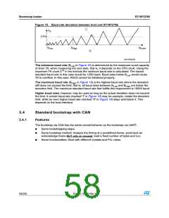
5.2.7
Exiting bootstrap loader mode
To execute a program in normal mode, the BSL mode must first be terminated. The
ST10F276E exits BSL mode at a software reset (level on P0L.4 is ignored) or a hardware
reset (P0L.4 must be high in this case). After the reset, the ST10F276E starts executing
from location 00’0000H of the internal Flash (User Flash) or the external memory, as
programmed via pin EA.
Note:
If a bidirectional software reset is executed and external memory boot is selected (EA = 0),
a degeneration of the software reset event into a hardware reset can occur (refer to
Section 19.3: Synchronous reset (warm reset) for details). This implies that P0L.4 becomes
transparent, so to exit from Bootstrap mode it would be necessary to release pin P0L.4 (it is
no longer ignored).
5.2.8
Hardware requirements
Although the new bootstrap loader is designed to be compatible with the old bootstrap
loader, there are a few hardware requirements relative to the new bootstrap loader:
–
–
External Bus configuration: Must have four or less segment address lines (keep
CAN I/Os available);
Usage of CAN pins (P4.5 and P4.6): Even in bootstrap via UART, P4.5
(CAN1_RxD) can be used as Port input but not as output. The pin P4.6
(CAN1_TxD) can be used as input or output.
–
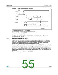
Level on UART RxD and CAN1_RxD during the bootstrap phase (see Figure 6 -
Step 2): Must be 1 (external pull-ups recommended).
5.3
Standard bootstrap with UART (RS232 or K-Line)
5.3.1
Features
ST10F276E bootstrap via UART has the same overall behavior as the old ST10 bootstrap
via UART:
●
Same bootstrapping steps
●
Same bootstrap method: Analyze the timing of a predefined byte, send back an
acknowledge byte, load a fixed number of bytes and run
●
Same functionalities: Boot with different crystals and PLL ratios
54/235
Doc ID 12303 Rev 3

 STMICROELECTRONICS [ ST ]