ST10F276E
Bootstrap loader
5.2.3
Booting steps
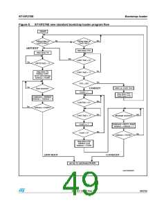
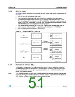
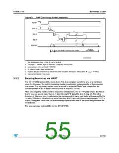
As Figure 6 shows, booting ST10F276E with the boot loader code occurs in a minimum of
four steps:
1. The ST10F276E is reset with P0L.4 low.
2. The internal new bootstrap code runs on the ST10 and a first level user code is
downloaded from the external device, via the selected serial link (UART0 or CAN1).
The bootstrap code is contained in the ST10F276E Test-Flash and is automatically run
when ST10F276E is reset with P0L.4 low. After loading a preselected number of bytes,
ST10F276E begins executing the downloaded program.
3. The first level user code runs on ST10F276E. Typically, this first level user code is
another loader that downloads the application software into the ST10F276E.
4. The loaded application software is now running.
Figure 6.
Booting steps for ST10F276E
3TEP ꢀ
%XTERNAL DEVICE
34 ꢀꢉ&ꢁꢊꢄ%
34 ꢀꢉ&ꢁꢊꢄ%
%NTERING BOOTSTRAP
$OWNLOAD
&IRST LEVEL USER CODE
%XTERNAL DEVICE
%XTERNAL DEVICE
%XTERNAL DEVICE
3TEP ꢁ
,OADING FIRST LEVEL USER CODE
2UN BOOTSTRAP CODE
FROM 4ESTꢅ&LASH
$OWNLOAD
!PPLICATION
34 ꢀꢉ&ꢁꢊꢄ%
3TEP ꢈ
,OADING THE APPLICATION
AND EXITING "3,
2UN FIRST LEVEL CODE
FROM $02!- &!ꢇꢉH
34 ꢀꢉ&ꢁꢊꢄ%
3TEP ꢇ
2UN APPLICATION CODE
'!0'2)ꢉꢉꢈꢁꢈ
5.2.4
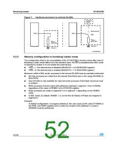
Hardware to activate BSL
The hardware that activates the BSL during reset may be a simple pull-down resistor on
P0L.4 for systems that use this feature at every hardware reset. For systems that use the
bootstrap loader only temporarily, it may be preferable to use a switchable solution (via
jumper or an external signal).
Note:
CAN alternate function on Port4 lines is not activated if the user has selected eight address
segments (Port4 pins have three functions: I/O port, address segment and CAN). Boot via
CAN requires that four or less address segments are selected.
Doc ID 12303 Rev 3
51/235

 STMICROELECTRONICS [ ST ]