Power reduction modes
ST10F276E
Before entering Power Down mode (by executing the instruction PWRDN), bit VREGOFF in
XMISC register must be set.
Note:
Leaving the main voltage regulator active during Power Down may lead to unexpected
behavior (ex: CPU wake-up) and power consumption higher than what specified.
20.2.1
Protected power down mode
This mode is selected when PWDCFG (bit 5) of SYSCON register is cleared. The Protected
Power Down mode is only activated if the NMI pin is pulled low when executing PWRDN
instruction (this means that the PWRD instruction belongs to the NMI software routine). This
mode is only deactivated with an external hardware reset on RSTIN pin.
20.2.2
Interruptible power down mode
This mode is selected when PWDCFG (bit 5) of SYSCON register is set.
The Interruptible Power Down mode is only activated if all the enabled Fast External
Interrupt pins are in their inactive level.
This mode is deactivated with an external reset applied to RSTIN pin or with an interrupt
request applied to one of the Fast External Interrupt pins, or with an interrupt generated by
the Real-Time Clock, or with an interrupt generated by the activity on CAN’s and I2C module
interfaces. To allow the internal PLL and clock to stabilize, the RSTIN pin must be held low
according the recommendations described in Chapter 19: System reset.
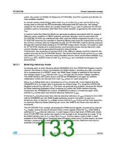
An external RC circuit must be connected to RPD pin, as shown in the Figure 43.
Figure 43. External RC circuitry on RPD pin
6
$$
34ꢀꢉ&ꢁꢊꢄ
2ꢉ
ꢁꢁꢉK: MINIMUM
20$
ꢑ
#ꢉ
ꢀP& 4YPICAL
'!02)ꢉꢉꢈꢈꢈ
To exit Power Down mode with an external interrupt, an EXxIN (x = 7...0) pin has to be
asserted for at least 40ns.
20.3
Stand-by mode
In Stand-by mode, it is possible to turn off the main VDD provided that VSTBY is available
through the dedicated pin of the ST10F276E.
To enter Stand-by mode it is mandatory to held the device under reset: once the device is
under reset, the RAM is disabled (see XRAM2EN bit of XPERCON register), and its digital
interface is frozen in order to avoid any kind of data corruption.
A dedicated embedded low-power voltage regulator is implemented to generate the internal
low voltage supply (about 1.65V in Stand-by mode) to bias all those circuits that shall remain
132/235
Doc ID 12303 Rev 3

 STMICROELECTRONICS [ ST ]