ST10F276E
System reset
WDTCON flags
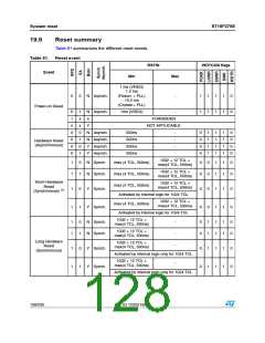
Table 61. Reset event (continued)
RSTIN
Event
Min
Max
x
x
0
1
x
x
0
1
0
0
1
1
0
0
1
1
N
N
Y
Y
N
N
Y
Y
Synch.
Synch.
Synch.
Synch.
Synch.
Synch.
Synch.
Synch.
Not activated
Not activated
Not activated
0
0
0
0
0
0
0
0
0
0
0
0
0
0
0
0
0
0
0
0
0
0
0
0
1
1
1
1
1
1
1
1
0
0
0
0
1
1
1
1
Software Reset (2)
Watchdog Reset (2)
Activated by internal logic for 1024 TCL
Not activated
Not activated
Not activated
Activated by internal logic for 1024 TCL
1. It can degenerate into a Long Hardware Reset and consequently differently flagged (see Section 19.3 for details).
2. When Bidirectional is active (and with RPD=0), it can be followed by a Short Hardware Reset and consequently differently
flagged (see Section 19.6 for details).
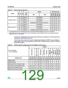
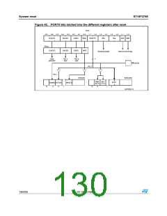
The start-up configurations and some system features are selected on reset sequences as
described in Table 62 and Figure 42.
Table 62 describes what is the system configuration latched on PORT0 in the six different
reset modes. Figure 42 summarizes the state of bits of PORT0 latched in RP0H, SYSCON,
BUSCON0 registers.
Table 62. PORT0 latched configuration for the different reset events
PORT0
X: Pin is sampled
-: Pin is not sampled
Sample event
Software Reset
-
-
-
-
-
-
X
X
X
X
X
X
X
X
X
X
X
X
X
X
X
X
X
X
X
X
X
X
X
X
X
X
X
X
X
X
X
X
X
X
X
X
X
X
X
X
X
X
-
-
-
-
-
-
Watchdog Reset
-
-
-
-
-
-
Synchronous Short Hardware Reset
Synchronous Long Hardware Reset
Asynchronous Hardware Reset
Asynchronous Power-On Reset
-
-
-
X
X
X
X
X
X
X
X
X
X
X
X
X
X
X
X
X
X
X
X
X
X
X
X
X
X
X
X
X
X
X
X
X
Doc ID 12303 Rev 3
129/235

 STMICROELECTRONICS [ ST ]