ST10F276E
Power reduction modes
20
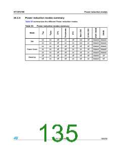
Power reduction modes
Three different power reduction modes with different levels of power reduction have been
implemented in the ST10F276E. In Idle mode only CPU is stopped, while peripheral still
operate. In Power Down mode both CPU and peripherals are stopped. In Stand-by mode
the main power supply (VDD) can be turned off while a portion of the internal RAM remains
powered via VSTBY dedicated power pin.
Idle and Power Down modes are software activated by a protected instruction and are
terminated in different ways as described in the following sections.
Stand-by mode is entered simply removing VDD, holding the MCU under reset state.
Note:
All external bus actions are completed before Idle or Power Down mode is entered.
However, Idle or Power Down mode is not entered if READY is enabled, but has not been
activated (driven low for negative polarity, or driven high for positive polarity) during the last
bus access.
20.1
Idle mode
Idle mode is entered by running IDLE protected instruction. The CPU operation is stopped
and the peripherals still run.
Idle mode is terminate by any interrupt request. Whatever the interrupt is serviced or not,
the instruction following the IDLE instruction will be executed after return from interrupt
(RETI) instruction, then the CPU resumes the normal program.
20.2
Power down mode
Power Down mode starts by running PWRDN protected instruction. Internal clock is
stopped, all MCU parts are on hold including the watchdog timer. The only exception could
be the Real-Time Clock if opportunely programmed and one of the two oscillator circuits as
a consequence (either the main or the 32 kHz on-chip oscillator).
When Real-Time Clock module is used, when the device is in Power Down mode a
reference clock is needed. In this case, two possible configurations may be selected by the
user application according to the desired level of power reduction:
●
A 32 kHz crystal is connected to the on-chip low-power oscillator (pins XTAL3 / XTAL4)
and running. In this case the main oscillator is stopped when Power Down mode is
entered, while the Real-Time Clock continue counting using 32 kHz clock signal as
reference. The presence of a running low-power oscillator is detected after the Power-
on: this clock is immediately assumed (if present, or as soon as it is detected) as
reference for the Real-Time Clock counter and it will be maintained forever (unless
specifically disabled via software).
●
Only the main oscillator is running (XTAL1 / XTAL2 pins). In this case the main
oscillator is not stopped when Power Down is entered, and the Real-Time Clock
continue counting using the main oscillator clock signal as reference.
There are two different operating Power Down modes: protected mode and interruptible
mode.
Doc ID 12303 Rev 3
131/235

 STMICROELECTRONICS [ ST ]