System reset
ST10F276E
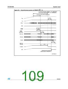
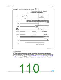
Figure 25. Asynchronous power-on RESET (EA = 0)
t ꢀꢌꢁMS ꢍFOR RESONATOR OSCILLATION ꢑ 0,, STABILIZATIONꢏ
t ꢀꢉꢌꢁMS ꢍFOR CRYSTAL OSCILLATION ꢑ 0,, STABILIZATIONꢏ
t ꢀMS ꢍFOR ONꢅCHIP 62%' STABILIZATIONꢏ
ꢍꢀꢏ
ꢈꢌꢌꢆ 4#,
6
$$
6
ꢀꢆ
ꢌꢌꢌ
84!,ꢀ
20$
t ꢃꢉ NS
dꢃꢉꢉ NS
234).
234&
ꢍAFTER FILTERꢏ
ꢈꢌꢌꢇ 4#,
4RANSPARENT
4RANSPARENT
.OT Tꢌ
.OT Tꢌ
0ꢉ;ꢀꢃꢐꢀꢈ=
0ꢉ;ꢀꢁꢐꢁ=
0ꢉ;ꢀꢐꢉ=
.OT TRANSPARENT
.OT Tꢌ
ꢆ 4#,
!,%
234
,ATCHING POINT OF PORTꢉ FOR
SYSTEM STARTꢅUP CONFIGURATION
'!0'2)ꢉꢉꢀꢉꢁ
1. 3 to 8 TCL depending on clock source selection.
Hardware reset
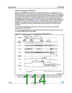
The asynchronous reset must be used to recover from catastrophic situations of the
application. It may be triggered by the hardware of the application (internal hardware logic
and application circuitry are described in Section 19.7: Reset circuitry and figures 37, 38
and 39). It occurs when RSTIN is low and RPD is detected (or becomes) low as well.
110/235
Doc ID 12303 Rev 3

 STMICROELECTRONICS [ ST ]