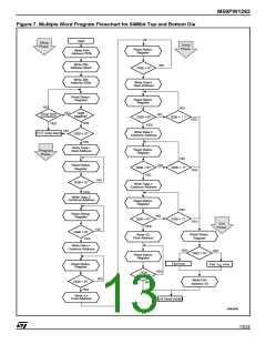
M59PW1282
DC AND AC PARAMETERS
This section summarizes the operating measure-
ment conditions, and the DC and AC characteris-
tics of the device. The parameters in the DC and
AC characteristics Tables that follow, are derived
from tests performed under the Measurement
Conditions summarized in Table 10, Operating
and AC Measurement Conditions. Designers
should check that the operating conditions in their
circuit match the operating conditions when rely-
ing on the quoted parameters.
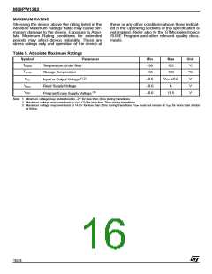
Table 10. Operating and AC Measurement Conditions
Parameter
M59PW1282
100, 120
Unit
Min
2.7
11.4
0
Max
3.6
V
V
Read Supply Voltage
V
V
CC
Program/Erase Supply Voltage
12.6
70
PP
Ambient Operating Temperature (T )
°C
pF
ns
V
A
Load Capacitance (C )
30
L
Input Rise and Fall Times
10
Input Pulse Voltages
0 to 3
1.5
Input and Output Timing Ref. Voltages
V
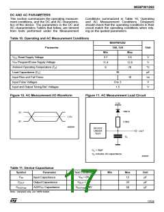
Figure 10. AC Measurement I/O Waveform
Figure 11. AC Measurement Load Circuit
1.3V
1N914
3V
1.5V
0V
3.3kΩ
AI05546
DEVICE
UNDER
TEST
OUT
C
L
C = 30pF
L
C includes JIG capacitance
L
AI05447
Table 11. Device Capacitance
Symbol
Parameter
Input Capacitance
Output Capacitance
Test Condition
Min
Max
12
Unit
pF
C
V
IN
= 0V
= 0V
IN
C
V
OUT
24
pF
OUT
C
A22/V Capacitance
V
= 0V
50
pF
A22/Vpp
PP
A22/Vpp
Note: Sampled only, not 100% tested.
17/24

 STMICROELECTRONICS [ ST ]