M59PW1282
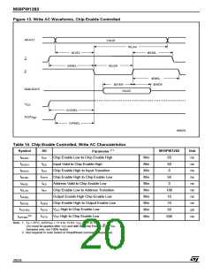
Figure 13. Write AC Waveforms, Chip Enable Controlled
A0-A21
VALID
tELAX
tAVEL
tEHGL
G
E
tGHEL
tELEH
tEHEL
tEHDX
tDVEH
VALID
DQ0-DQ15
V
CC
tVCHEL
tVPHEL
A22/V
PP
AI08233
Table 14. Chip Enable Controlled, Write AC Characteristics
(1)
Symbol
Alt
M59PW1282
Unit
ns
ns
ns
ns
ns
ns
ns
ns
µs
Parameter
Chip Enable Low to Chip Enable High
Input Valid to Chip Enable High
t
t
Min
Min
Min
Min
Min
Min
Min
Min
Min
50
50
0
ELEH
CP
t
t
DVEH
DS
t
t
Chip Enable High to Input Transition
Chip Enable High to Chip Enable Low
Address Valid to Chip Enable Low
Chip Enable Low to Address Transition
Output Enable High Chip Enable Low
Chip Enable High to Output Enable Low
EHDX
DH
t
t
50
0
EHEL
CPH
t
t
AS
AVEL
t
t
AH
100
10
10
50
ELAX
t
GHEL
t
t
EHGL
OEH
t
t
t
V
V
High to Chip Enable Low
High to Chip Enable Low
VCHEL
VCS
CC
(2)
Min
500
ns
t
VCS
PP
VPHEL
Note: 1. T = 25°C; A22/V = 11.4 to 12.6V; V = 2.7 to 3.6V.
A
PP
CC
V
must be applied after V and with the Chip Enable (E) at V .
PP
CC IH
Sampled only, not 100% tested.
2. Not required in Auto Select or Read/Reset command sequences.
20/24

 STMICROELECTRONICS [ ST ]