M41T00
Device operation
2
Device operation
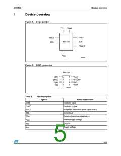
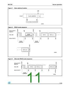
The M41T00 clock operates as a slave device on the serial bus. Access is obtained by
implementing a start condition followed by the correct slave address (D0h). The 8 bytes
contained in the device can then be accessed sequentially in the following order:
st
1 byte: seconds register
nd
2
3
byte: minutes register
rd
th
byte: century/hours register
4 byte: day register
th
5 byte: date register
th
6 byte: month register
th
7 byte: years register
th
8 byte: control register
The M41T00 clock continually monitors V for an out of tolerance condition. Should V
CC
CC
fall below V , the device terminates an access in progress and resets the device address
SO
counter. Inputs to the device will not be recognized at this time to prevent erroneous data
from being written to the device from an out of tolerance system. When V falls below V
,
CC
SO
the device automatically switches over to the battery and powers down into an ultra low
current mode of operation to conserve battery life. Upon power-up, the device switches from
battery to V at V and recognizes inputs.
CC
SO
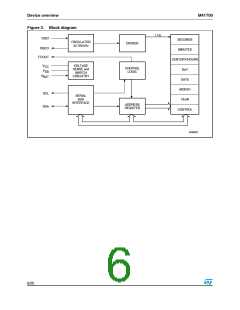
2.1
Wire bus characteristics
This bus is intended for communication between different ICs. It consists of two lines: one
bi-directional for data signals (SDA) and one for clock signals (SCL). Both the SDA and the
SCL lines must be connected to a positive supply voltage via a pull-up resistor.
The following protocol has been defined:
●
Data transfer may be initiated only when the bus is not busy.
●
During data transfer, the data line must remain stable whenever the clock line is High.
Changes in the data line while the clock line is High will be interpreted as control
signals.
Accordingly, the following bus conditions have been defined:
2.2
2.3
Bus not busy
Both data and clock lines remain high.
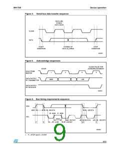
Start data transfer
A change in the state of the data line, from high to low, while the clock is high, defines the
START condition.
7/25

 STMICROELECTRONICS [ ST ]