DC and AC parameters
M41T00
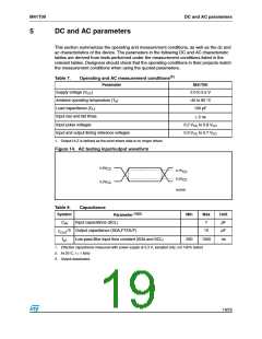
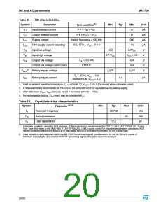
Table 9.
Symbol
DC characteristics
Test condition(1)
Parameter
Input leakage current
Output leakage current
Supply current
Min
Typ
Max
Unit
µA
µA
µA
µA
V
ILI
0 V = VIN = VCC
1
1
ILO
0 V = VOUT = VCC
ICC1
ICC2
VIL
Switch frequency = 100 kHz
SCL, SDA = VCC – 0.3 V
300
RTC supply current (standby)
Input low voltage
70
0.3VCC
VCC + 0.5
–0.3
VIH
VOL
0.7 VCC
Input high voltage
V
IOL = 3.0 mA
Output low voltage
0.4
5.5
V
Output low voltage (open drain)
Battery supply voltage
FT/OUT
V
(2)
2.5(3)
3.5(4)
V
VBAT
TA = 25 °C, VCC = 0 V
oscillator ON, VBAT = 3 V
IBAT
Battery supply current
0.8
1
µA
1. Valid for ambient operating temperature: TA = –40 to 85 °C; VCC = 2.0 to 5.5 V (except where otherwise noted).
2. STMicroelectronics recommends the RAYOVAC BR1225 or BR1632 (or equivalent)as the battery supply.
3. After switchover (VSO), VBAT(min) can be 2.0 V for crystal with RS = 40 KΩ.
4. For rechargeable backup, VBAT(max) may be considered VCC
.
Table 10. Crystal electrical characteristics
Parameter (1)(2)
Symbol
Min
Typ
Max
Units
kHz
KΩ
fO
RS
CL
Resonant frequency
Series resistance
Load capacitance
32.768
60
12.5
pF
1. Externally supplied if using the SO8 package. STMicroelectronics recommends the KDS DT-38: 1TA/1TC252E127, Tuning
Fork Type (thru-hole) or the DMX-26S: 1TJS125FH2A212, (SMD) quartz crystal for industrial temperature operations. KDS
can be contacted at kouhou@kdsj.co.jp or http://www.kdsj.co.jp for further information on this crystal type.
2. Load capacitors are integrated within the M41T00. Circuit board layout considerations for the 32.768 kHz crystal of
minimum trace lengths and isolation from RF generating signals should be taken into account.
20/25

 STMICROELECTRONICS [ ST ]