L6599A
Application information
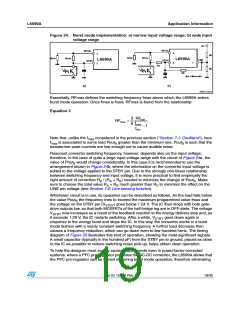
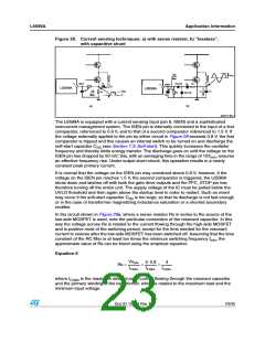
Figure 28. Current sensing techniques: a) with sense resistor, b) “lossless”,
with capacitive shunt
ꢀ
ꢂꢋ
I
PLQ
9&USN
ꢁ ꢁ
&U
ꢂ1ꢈꢂꢈꢄ
&
5$
'$3ꢋꢂꢉ ꢅꢁꢁꢁꢁꢁꢁ,6(1
$
ꢅꢁꢁꢁꢁꢁꢁ,6(1
,
&U
'$3ꢋꢂꢉ
/ꢅꢉꢍꢍ$
/ꢅꢉꢍꢍ$
9VSN
ꢋ
,
&U
ꢂꢋ
I
PLQ
&U
5V
5%
ꢂ1ꢈꢂꢈꢄ
ꢁ ꢁ
&
%
Dꢎ
Eꢎ
!-ꢀꢁꢁꢆꢃVꢁ
The L6599A is equipped with a current sensing input (pin 6, ISEN) and a sophisticated
overcurrent management system. The ISEN pin is internally connected to the input of a first
comparator, referenced to 0.8 V, and to that of a second comparator referenced to 1.5 V. If
the voltage externally applied to the pin by either circuit in Figure 28 exceeds 0.8 V, the first
comparator is tripped and this causes an internal switch to be turned on and discharge the
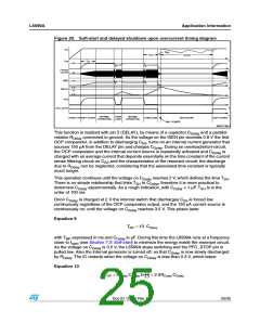
soft-start capacitor CSS (see Section 7.3: Soft-start). This quickly increases the oscillator
frequency and thereby limits energy transfer. The discharge goes on until the voltage on the
ISEN pin has dropped by 50 mV; this, with an averaging time in the range of 10/fmin, ensures
an effective frequency rise. Under output short-circuit, this operation results in a nearly
constant peak primary current.
It is normal that the voltage on the ISEN pin may overshoot above 0.8 V; however, if the
voltage on the ISEN pin reaches 1.5 V, the second comparator is triggered, the L6599A
shuts down and latches off with both the gate drive outputs and the PFC_STOP pin low,
therefore turning off the entire unit. The supply voltage of the IC must be pulled below the
UVLO threshold and then again above the startup level in order to restart. Such an event
may occur if the soft-start capacitor CSS is too large, so that its discharge is not fast enough
or in the case of transformer magnetizing inductance saturation or a shorted secondary
rectifier.
In the circuit shown in Figure 28a, where a sense resistor Rs in series to the source of the
low-side MOSFET is used, note the particular connection of the resonant capacitor. In this
way the voltage across Rs is related to the current flowing through the high-side MOSFET
and is positive most of the switching period, except for the time needed for the resonant
current to reverse after the low-side MOSFET has been switched off. Assuming that the time
constant of the RC filter is at least ten times the minimum switching frequency fmin, the
approximate value of Rs can be found using the empirical equation:
Equation 6
Vspkx
ICrpkx
5⋅0.8
ICrpkx
4
Rs =
≈
≈
ICrpkx
where ICrpkx is the maximum desired peak current flowing through the resonant capacitor
and the primary winding of the transformer, which is related to the maximum load and the
minimum input voltage.
Doc ID 15308 Rev 7
23/35

 STMICROELECTRONICS [ ST ]